What Is Valve Sealing Performance?
Valve sealing performance is the ability of a valve to prevent or limit fluid leakage at defined sealing locations under specified operating conditions. In industrial valve engineering, "sealing performance" is not a single number. It is the combined behavior of multiple sealing interfaces inside and outside the valve, each of which can respond differently to changes in media, pressure, temperature, cycling, and mechanical condition.
A valve that provides acceptable seat leakage at room temperature with water may show different leakage behavior with gas, at elevated temperature, or after extended cycling. For this reason, sealing performance should always be evaluated against the actual service conditions and the applicable acceptance criteria, not only against a nominal pressure class or catalogue rating.
How Valve Sealing Actually Works
Effective valve sealing depends on the interaction between two mating surfaces or sealing elements under sufficient contact load. At a macroscopic level, the closure member (ball, gate, disc, or plug) presses against a seat to block flow. At a microscopic level, however, no engineering surface is perfectly smooth. Every seating surface has peaks, valleys, and small irregularities created by machining, finishing, and material structure.
If the contact between the closure member and seat does not create sufficient and continuous surface conformity, connected microscopic leakage paths can allow fluid to pass through the interface. Whether these paths are sealed depends on several interacting factors:
- Contact pressure: The force per unit area between the closure member and seat. Insufficient contact pressure allows leakage; excessive contact pressure may cause deformation, friction, galling, or accelerated wear.
- Surface conformity: The ability of the seat material to conform to the closure member surface. Soft seats rely on elastic deformation; metal seats rely on precise machining and surface finish.
- Surface finish: Roughness, scratches, pitting, or machining marks on the seating surface create leakage paths. Smoother surfaces generally seal more effectively but may require specific materials or coatings to prevent galling.
- Closure force: The actuator torque or mechanical force that drives the closure member into the seat. The closure force must overcome differential pressure, seat friction, and any mechanical resistance.
- Differential pressure: The pressure difference across the closed valve. Differential pressure changes the forces acting on the closure member and seats. Depending on the valve and seat design, it may assist sealing, change seat load, or increase the torque or thrust required to operate and close the valve.
- Material elasticity and deformation: Soft seat materials deform elastically to fill surface irregularities. Metal seats depend on surface finish and contact stress. Both can undergo permanent deformation under sustained load, temperature, or cycling.
- Thermal expansion: Temperature changes alter clearances, contact stress, and material properties. Differential expansion between the closure member and seat can improve or degrade sealing depending on the design.
- Wear and surface damage: Any change to the original seating surface condition (erosion, scoring, abrasion, pitting) can open or widen leakage paths.
Higher seating force is not universally better. Excessive contact load can increase operating torque, cause seat deformation or creep, promote galling on metal-to-metal seats, and accelerate wear. The correct seating load depends on the valve design, seat material, pressure class, and applicable acceptance criteria.
Internal Leakage vs External Leakage
Valve leakage falls into two broad categories, and the engineering response to each is different. Treating all leakage as the same phenomenon can lead to incorrect material selection, wrong test specification, or missed compliance requirements.
Seat or Closure Leakage (Internal Leakage)
Seat leakage is flow through the closed valve closure member from upstream to downstream. In a ball valve, this is leakage past the ball-seat interface. In a gate valve, it is leakage past the gate-seat interface. In a globe valve, it is leakage past the disc-seat interface. Seat leakage is the most commonly specified valve leakage criterion and is typically verified by a seat pressure test per standards such as API 598, API 6D, ISO 5208, or MSS SP-61.
Shell or Pressure-Boundary Leakage (External Leakage)
Shell leakage is external leakage through the pressure-containing envelope of the valve: the body, bonnet, body-bonnet joint, body-end connections, or other pressure-boundary joints. A shell test (also called a body test or hydrostatic shell test) verifies the structural integrity and pressure-tightness of the pressure boundary. Passing a seat test does not prove that the pressure boundary is leak-free, and the two tests serve different purposes.
Stem or Packing Leakage (External Leakage)
Stem or packing leakage is external leakage around the stem or shaft where it exits the valve bonnet. The stem seal (packing, live-loaded packing, bellows seal, or other arrangement) must contain process pressure while allowing the stem to move. Packing leakage is one of the most common external leakage paths in rising-stem valves and is the primary focus of fugitive emission testing standards such as ISO 15848-1, ISO 15848-2, API 622, API 624, and API 641.
Body-Joint and Gasket Leakage (External Leakage)
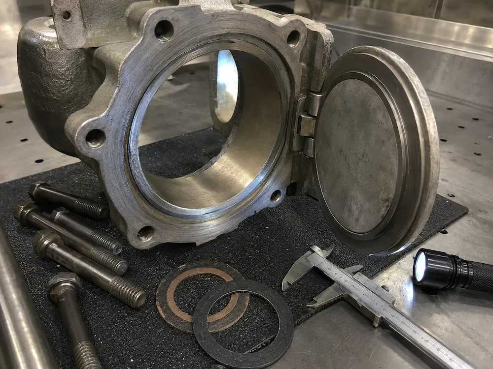
Body-bonnet joints, body-end connections, and other bolted joints rely on gaskets, spiral-wound seals, or metal-to-metal contact to prevent external leakage. Gasket condition, bolt preload, flange finish, and thermal cycling all affect joint leakage performance.
Fugitive Emissions
Fugitive emissions are a specialist category of atmospheric leakage from valve stem seals, body joints, and other defined external leakage paths. Fugitive emission requirements are governed by specific qualification and production-acceptance standards and should not be confused with general seat or shell leakage criteria. A valve that passes a fugitive emission test still requires satisfactory seat and shell test results for the applicable service. For a detailed explanation of the applicable standards, see the valve fugitive emission testing guide.
Why Valve Sealing Changes in Service
Several independent factors can cause sealing performance to change between the factory test condition and actual service, or to deteriorate over time in operation:
- Process media: Chemical compatibility, viscosity, lubricity, and solids content all affect seat and packing behavior.
- Operating pressure and differential pressure: Differential pressure changes the forces acting on the closure member and seats. Depending on the valve and seat design, it may assist sealing, change seat load, or increase the torque or thrust required to operate and close the valve.
- Temperature: Thermal expansion changes clearances, softens or hardens seat materials, and affects packing resilience.
- Seat material condition: Seats can degrade by corrosion, erosion, abrasion, swelling, or thermal aging.
- Surface finish: Seat surface roughness directly affects the ability of soft or metal seats to conform and seal.
- Valve design: Different closure geometries (ball, gate, disc, plug) create different sealing interfaces and different sensitivity to operating variables.
- Actuator or closing force: Insufficient torque or closing force can prevent the closure member from reaching the correct seating position.
- Installation: Pipe stress, misalignment, incorrect bolt tightening, and inadequate support can distort the valve body and affect seat contact.
- Contamination and debris: Particles trapped between the closure member and seat prevent full contact and create leakage paths.
- Cycling and wear: Repeated operation wears seats, deforms sealing surfaces, compresses packing, and may change operating torque.
These factors often act together. A valve in hot abrasive slurry service faces simultaneous challenges from temperature, abrasion, particle entrapment, and chemical attack that are not captured by a room-temperature water test.
How Different Media Affect Valve Sealing
Service media can influence sealing performance through several mechanisms, and the same valve may show different leakage behavior with different media even at the same pressure and temperature.
| Working Medium | Relevant Sealing Mechanisms | Commonly Considered Material Options | Key Specification Notes |
|---|---|---|---|
| Clean water | Low chemical attack; possible scaling or corrosion depending on water quality | EPDM, NBR, PTFE, stainless steel trim | Confirm water chemistry, chlorides, and temperature; EPDM suitability depends on specific water conditions |
| Oil or hydrocarbons | Viscosity affects torque; NBR or FKM swelling risk; permeation through elastomers | NBR, FKM, PTFE, graphite, stainless steel trim | Verify oil type, aromatic content, and temperature; NBR may not suit all hydrocarbon compositions |
| Gas | Gas and liquid can show different leakage behavior through very small clearances because their physical properties and the applicable test conditions differ; gas testing may reveal measurable leakage that is not observed in the same way during liquid testing; high sensitivity to seat finish and packing condition | PTFE, RPTFE, metal seat for severe service; appropriate packing | Seat finish and packing integrity are critical; specify seat leakage class and test medium |
| Steam | High temperature; thermal cycling; soft-seat degradation; packing relaxation | Graphite packing, metal seat, high-temperature trim | Confirm saturation or superheat condition; soft seats may have limited temperature capability |
| Acid or alkali | Corrosion; chemical attack on seats, packing, and body; possible swelling | PTFE, PFA, lined body, alloy 20, Hastelloy, duplex | Specify concentration, temperature, and phase; PTFE is commonly considered but mechanical load limits apply |
| Slurry or media with solids | Abrasion; particle entrapment between seat and closure member; erosion | Hard-faced or metal seats, rubber lining, hard trim | Specify solids content, particle size, and flow velocity; soft seats may not be suitable |
None of the materials listed above are universally suitable for the entire media category. Final seat and packing selection should be confirmed against the actual chemical composition, concentration, temperature, pressure, and mechanical load for the specific application, with reference to manufacturer data and applicable standards.
Seat, Seal, Packing, and Gasket Materials
Different sealing components in a valve serve different functions and face different service conditions:
- Seat material forms the primary closure seal between the ball, gate, disc, or plug and the valve body. Seats may be soft (PTFE, RPTFE, PEEK, PFA, EPDM, NBR, FKM, or other elastomers or polymers) or metal (stainless steel, Stellite, tungsten carbide, or other hardfacing). Soft seats can provide tight shutoff in clean compatible service but have temperature, pressure, and chemical limits. Metal seats are commonly considered for high temperature, abrasive, or severe service but may require higher closing force and may not achieve the same leakage class as a soft seat in clean service. For a detailed comparison, see the soft seat vs metal seat ball valve guide.
- Packing seals the stem or shaft where it exits the bonnet. Common packing materials include graphite, PTFE, and aramid fiber. Packing must allow stem movement while containing process pressure. Packing condition, gland bolt tension, and live-loading design all affect stem leakage.
- Gaskets seal bolted body joints, body-bonnet connections, and body-end connections. Gasket type (spiral wound, ring joint, flat, compressed sheet) and material must match the pressure class, temperature, and process media.
- O-rings and lip seals are used in some valve designs for stem sealing, body sealing, or seat backing. Material compatibility with the process media and temperature is essential.
For broader material selection guidance, see the valve material selection guide and the valve trim materials guide.
Seat Design Factors That Control Sealing Performance
Sealing performance is not determined by seat material alone. The geometry, surface condition, loading mechanism, and interaction with the closure member all affect whether the valve can maintain acceptable leakage under operating conditions.
Seat Geometry and Contact Area
Seat geometry and contact width influence the contact pressure between the closure member and seat, the ability of the seat to conform to the ball, gate, or disc, the sensitivity to contamination, the operating torque or closing force, and the wear behavior over time. A narrower contact area may produce higher contact pressure but may be more sensitive to surface damage or debris. A wider contact area may distribute load but may require more closing force. No single seat geometry is universally superior; the design is optimized for the valve type, pressure class, and intended service.
Surface Finish and Machining Quality
Sealing depends on the quality and condition of both mating surfaces. Surface roughness, scratches, pitting, machining marks, or handling damage can create connected leakage paths. For metal-to-metal seats, surface finish is particularly critical and may require lapping, polishing, or specific coating or hardfacing to achieve the required contact quality. For soft seats, the seat material can sometimes conform to minor closure-member surface irregularities, but significant surface damage will still compromise sealing. Surface-finish requirements vary by valve type, seat material, and acceptance standard and should not be assumed from generic guidelines.
Soft Seat vs Metal Seat
Soft or resilient seats can conform to small surface irregularities and may provide very tight shutoff in compatible, clean service at moderate temperature and pressure. Metal seats provide improved resistance to temperature, abrasion, and severe mechanical conditions when correctly designed, but leakage performance depends on seat design, surface condition, loading, and the applicable acceptance criteria. Neither type is universally better. For a detailed comparison, see the soft seat vs metal seat ball valve guide.
Seating Force and Differential Pressure
Sealing behavior depends on the mechanical closing force, actuator torque or thrust, differential pressure across the seat, valve design, and any seat preload built into the design. Some valve designs use line pressure to assist seating (for example, floating ball valves where upstream pressure pushes the ball against the downstream seat), but pressure-assisted sealing is design-specific and should not be generalized to every valve type. Trunnion-mounted ball valves, gate valves, globe valves, and check valves use different seating mechanisms, and the relationship between differential pressure and seat load differs in each case.
Pressure, Temperature, and Differential Pressure
Pressure rating alone does not determine sealing performance. Several pressure and temperature factors interact:
- Operating pressure vs test pressure: Factory pressure-test pressures, durations, test media, and acceptance criteria are defined by the applicable valve product or test standard and the specific valve design and rating. They should not be assumed from one universal pressure multiplier. Actual operating pressure may differ from test pressure, and differential pressure across the closed valve influences the forces acting on the closure member, seats, and operating mechanism according to the specific valve design.
- Maximum differential pressure: In some installations, the full upstream pressure can appear across the closed valve while the downstream is depressurized. The actuator or operator must provide enough force to seat the closure member under this maximum differential pressure.
- Temperature effects: Elevated temperature can reduce seat material strength, cause thermal expansion that changes clearances, relax packing preload, and accelerate chemical attack. Low temperature can embrittle some elastomers. The pressure-temperature rating of the valve body does not by itself define the seat or packing temperature limit.
- Thermal cycling: Repeated heating and cooling can cause differential expansion, gasket relaxation, bolt load changes, and packing leakage.
- Closing force: Actuator torque or manual operator force must overcome line pressure, seat friction, and any mechanical resistance to reach the correct seating position. If the closing force is insufficient, the valve may not achieve the expected seat leakage class.
For pressure testing methods and acceptance criteria, see the valve pressure test methods guide.
Valve Type and Sealing Behavior
Different valve designs use different closure geometries, and sealing behavior depends on the specific design, not only on the valve type name:
| Valve Type | Closure Design | Sealing Considerations |
|---|---|---|
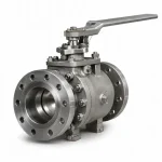
| Ball valve | Spherical ball rotates against annular seats | Can provide tight shutoff with appropriate seat design and condition. Seat wear, debris, throttling, and temperature can affect performance. Soft seats are common in clean service; metal seats are used for severe or abrasive service. See ball valve category. |
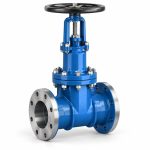
| Gate valve | Flat or wedge gate moves perpendicular to flow | Generally used for isolation, not throttling. Seat condition, debris between gate and seat, and alignment affect closure leakage. Rising-stem designs require packing integrity. See gate valve category. |
| Globe valve | Disc moves against a seat ring in the flow path | Different closure geometry from ball or gate valves. Commonly selected where throttling or frequent adjustment is part of the design intent. Seat leakage depends on disc condition, seat condition, and closing force. |
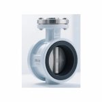
| Butterfly valve | Disc rotates in the flow path | Leakage performance depends strongly on seat design (lined vs high-performance), disc geometry, material, pressure class, and application. See butterfly valve category. |
| Check valve | Disc, plate, ball, or piston closes on reverse flow | Sealing depends on reverse differential pressure, closure dynamics, valve orientation where applicable, and the specific closure design. Insufficient reverse differential pressure may result in limited seating force in some designs. See check valve category. |
No valve type is universally superior in sealing performance. The correct choice depends on the service conditions, leakage requirement, operating duty, and maintenance expectations.
Why a Valve Can Pass Factory Testing and Still Leak in Service
This is one of the most important sealing concepts for industrial buyers. Factory pressure testing verifies that the valve meets defined acceptance criteria under specified test conditions. It does not guarantee identical leakage performance under all possible service conditions. Several differences between factory test and real service can explain a change in leakage behavior:
- Test medium vs service medium: Factory seat tests use specified liquid or gas test media under conditions defined by the applicable standard or project requirement. Actual service may involve different media, temperatures, differential pressures, contamination, and operating cycles. Gas and liquid can show different leakage behavior through very small clearances because their physical properties and the applicable test conditions differ. Gas testing may reveal measurable leakage that is not observed in the same way during liquid testing. Chemical media may attack seat or packing materials that are compatible with water.
- Temperature: Factory tests are typically at ambient temperature. Service at elevated temperature can reduce seat material strength, relax packing, change clearances through thermal expansion, and accelerate chemical attack.
- Differential pressure: The test differential pressure may differ from the maximum operating differential pressure. If the actuator or operator cannot provide enough force at the actual differential pressure, the closure member may not seat fully.
- Debris and contamination: Factory tests use clean valves on clean test stands. Service pipelines may contain weld spatter, scale, sand, or other debris that can damage seats on first operation.
- Installation stress: Pipe misalignment, inadequate supports, or incorrect bolt tightening can distort the valve body and change seat contact. Factory tests do not include pipe loads.
- Cycling: Factory acceptance testing does not reproduce the long-term cycling, wear, seat deformation, packing relaxation, contamination, or thermal history that may develop during extended field service.
- Packing and gasket condition: Packing that is correctly adjusted at the factory may relax under temperature cycling or vibration in service. Gaskets may creep or relax under thermal and pressure cycling.
This does not mean factory testing is unreliable. Factory testing verifies that the valve, as manufactured, meets the specified acceptance criteria under the specified test conditions. The engineering task is to ensure that the specified test conditions and acceptance criteria are appropriate for the actual service, and that the valve design and materials are suitable for the conditions the valve will face in operation. For pre-shipment verification procedures, see the valve factory acceptance test guide.
Damage Mechanisms That Degrade Valve Sealing
Understanding how seating surfaces, packing, and gaskets degrade helps buyers select materials and inspection intervals that match the actual service. The following table summarizes common damage mechanisms and their sealing consequences.
| Damage Mechanism | What Happens | Typical Sealing Consequence | What Buyers Should Check |
|---|---|---|---|
| Abrasion | Particles in the media scratch or wear sealing surfaces | Progressive seat leakage, especially in slurry, catalyst, scale, sand, or contaminated service | Solids content, particle size, flow velocity, and seat hardness or lining compatibility |
| Erosion | High-velocity flow removes material from seating surfaces | Seat damage worsens with continued operation, increasing leakage | Flow velocity, pressure drop, valve position in pipeline, and seat or hardfacing material |
| Corrosion | Chemical attack creates pitting, material loss, or surface irregularity | Pitted or roughened seating surface allows leakage; may also weaken the body | Medium composition, concentration, temperature, and material compatibility |
| Cavitation or Flashing | Severe local fluid conditions can damage downstream or trim surfaces | Surface pitting or material removal on seating surfaces or adjacent trim | Pressure differential, valve type suitability, and whether service conditions can cause cavitation or flashing |
| Scoring and Galling | Metal contact, contamination, inadequate material pairing, or severe loading damages metal sealing surfaces | Linear scratches or adhesive wear on seats, increasing leakage | Material pairing, surface finish, lubrication, and whether the valve is used within its design limits |
| Particle Entrapment | Debris between closure member and seat prevents full contact | Immediate leakage path; embedded particles can permanently damage the seat | Pipeline cleanliness, strainer or filter installation, and commissioning procedure |
| Thermal Cycling | Repeated temperature change affects clearances, gasket compression, bolt loading, packing condition, and seat contact | Progressive seat or packing leakage after heating-cooling cycles | Operating temperature range, cycling frequency, and material behavior at temperature extremes |
| Polymer Deformation or Creep | Soft seats permanently deform under combinations of load, temperature, pressure, and time | Seat loses original geometry, resulting in increased leakage | Seat material temperature and pressure limits, mechanical load, and manufacturer data |
| Packing Relaxation | Packing load changes during service due to cycling, temperature, vibration, or material behavior | Stem leakage develops or increases over time | Packing material, live-loading design, gland adjustment, and inspection interval |
These mechanisms often act in combination. For example, a valve in abrasive slurry service may experience abrasion, particle entrapment, and erosion simultaneously. For troubleshooting guidance when leakage has already occurred, see the valve problems troubleshooting guide.
Common Causes of Valve Leakage
When a valve leaks in service, the root cause often involves more than one factor. The following diagnostic table provides possible causes to investigate. It is not a definitive diagnosis and does not replace formal inspection or troubleshooting procedures.
| Observed Leakage | Possible Cause | What To Verify |
|---|---|---|
| Seat leakage immediately after installation | Debris, incorrect closure position, pipe stress, seat damage during transit or installation, incorrect actuator adjustment | Pipeline cleanliness, valve closure position, flange alignment and bolt torque, actuator stroke and limit switch setting, seat surface condition |
| Seat leakage after service period | Wear, erosion, corrosion, seat deformation or creep, throttling damage, thermal cycling | Seat surface condition, operating history, media solids content, temperature cycling, whether valve was used for throttling |
| Stem leakage | Packing condition, gland adjustment, material incompatibility, stem surface condition, thermal cycling, vibration | Packing material and condition, gland bolt torque, stem surface finish, operating temperature, packing live-loading design |
| Body-joint leakage | Gasket damage or wrong type, insufficient bolt preload, joint misalignment, thermal cycling, pressure boundary condition | Gasket type and condition, bolt torque pattern and preload, flange alignment, joint surface condition, thermal history |
One additional cause not reflected in the table above is incorrect material selection - seat, packing, gasket, or body material not compatible with the actual process media, temperature, or pressure. For troubleshooting guidance when leakage has already occurred, see the valve problems troubleshooting guide.
How Buyers Should Specify Sealing Requirements
Many valve leakage problems originate from incomplete or imprecise specification at the ordering stage. A technically complete sealing requirement should address the following:
- Leakage type: Specify whether the requirement applies to seat (closure) leakage, shell (pressure boundary) leakage, stem packing leakage, or fugitive emissions. Each is tested differently and governed by different standards.
- Acceptance criterion: Define the acceptable leakage rate or class (for example, API 598 allowable leakage, ISO 5208 rate class, or FCI 70-2 leakage class for control valves). Avoid "zero leakage" unless the test method and measurement sensitivity are also defined.
- Test standard: Identify the applicable test standard (API 598, API 6D, ISO 5208, MSS SP-61, or other) and the test medium, test pressure, and test duration.
- Service conditions: Provide the actual operating medium, pressure, temperature, differential pressure, and operating frequency so the manufacturer can confirm material and design suitability.
- Material requirements: Specify body, trim, seat, packing, and gasket materials where the service requires particular compatibility. Do not assume that a standard material offering is suitable for every service.
- Special requirements: Identify fugitive emission requirements, fire-safe requirements, NACE MR0175 / ISO 15156 material requirements where applicable to the specified sour-service environment, or other special qualification requirements that affect sealing design and testing. Sour-service material requirements should be confirmed by project review and should not be assumed to apply to every valve or every H2S-containing application.
Valve Sealing RFQ Checklist
When requesting a quotation for valves where sealing performance is critical, include the following information:
| Requirement | Why It Matters for Sealing |
|---|---|
| Valve type and size | Determines closure geometry and seat design |
| Pressure class or PN | Defines pressure boundary and test pressure |
| Process media and concentration | Affects material compatibility and leakage mechanism |
| Operating pressure and maximum differential pressure | Influences seating forces and required operating torque or thrust according to valve design |
| Operating temperature and design temperature | Affects seat material limits, packing performance, and thermal expansion |
| Required seat or closure leakage criterion | Defines the acceptable leakage rate and test method |
| Applicable test standard and test medium | Ensures consistent verification between buyer and manufacturer |
| Body, trim, seat, and packing material | Directly determines chemical compatibility and temperature capability |
| Fugitive emission requirement (if applicable) | Specifies the applicable standard, qualification scope, and acceptance level |
| Fire-safe requirement (if applicable) | Affects seat design and material selection |
| Inspection and documentation requirements | Ensures traceability and verification of sealing performance |
FAQ
What affects valve sealing performance?
The main factors are process media, seat material and condition, packing condition, pressure, differential pressure, temperature, surface finish, valve design, actuator or closing force, installation quality, and contamination. These factors often interact, and a change in any one can affect leakage behavior.
Why can a valve pass factory testing but leak in service?
Factory testing verifies defined acceptance criteria using specified liquid or gas test media under conditions established by the applicable standard or project requirement. Service conditions may involve different media, higher temperature, different differential pressure, debris, pipe stress, and cycling that were not present during the factory test. The factory test confirms the valve meets the specified criteria at the specified conditions; it does not guarantee performance under all possible service conditions.
What is the difference between seat leakage and external leakage?
Seat leakage (internal leakage) is flow through the closed valve closure member from upstream to downstream. External leakage is release of process fluid to the environment through the pressure boundary, stem packing, body joints, or gasketed connections. The two are tested separately, governed by different standards, and require different corrective actions.
How does process media affect valve sealing?
Process media affects sealing through chemical compatibility with seat and packing materials, viscosity and lubricity, different leakage behavior between gas and liquid through very small clearances, temperature effects, solids content (abrasion and particle entrapment), and potential for corrosion or swelling. The same valve may show different leakage behavior with different media at the same pressure and temperature.
Can soft-seated valves provide tighter shutoff than metal-seated valves?
In clean, compatible service at moderate temperature and pressure, soft seats can often achieve tighter shutoff than metal seats because the resilient seat material conforms to minor surface irregularities on the closure member. However, soft seats have temperature, pressure, and chemical limits. Metal seats are commonly required for high temperature, abrasive, or severe service where soft seats would degrade. Neither design is universally better; selection depends on the actual service conditions.
How can debris affect valve seat leakage?
Debris trapped between the closure member and the seat prevents full contact and creates a leakage path. Even small particles can cause measurable seat leakage, and gas testing may reveal leakage that is not observed in the same way during liquid testing. Debris can also score or embed in the seat surface, causing permanent damage that worsens with further cycling. Pipeline cleaning before commissioning and appropriate strainer or filter installation help reduce debris-related leakage.
Which factors should be specified for valve leakage requirements?
Specify the leakage type (seat, shell, packing, or fugitive emission), the acceptance criterion or leakage class, the applicable test standard and test medium, the actual service conditions (media, pressure, temperature, differential pressure), the required materials, and any special requirements such as fugitive emission or fire-safe qualification. Incomplete specification is a common source of leakage problems after installation.
Final Buyer Guidance
Valve sealing performance should be evaluated against the actual service conditions, not only against a catalogue pressure rating or a single factory test result. Before ordering valves for chemical, gas, steam, slurry, or corrosive service, confirm the process medium, temperature, pressure, differential pressure, leakage requirement, applicable test standard, material compatibility, and any special qualification requirements.
For a technically complete quotation, use the RFQ checklist above and include the operating conditions that affect sealing. Contact Vcore Valve with your project requirements for material confirmation and sealing performance guidance.