Quick overview
Replacing an existing pressure safety valve is not always a like-for-like purchase. The original inlet size, outlet size and orifice area may not provide sufficient certified relieving capacity for the current process conditions. When engineers recalculate the required capacity, they may recommend a larger orifice and, in some cases, different inlet and outlet connections. This article explains how safety valve replacement sizing affects valve selection, piping compatibility and project procurement.
1. Why Is Safety Valve Replacement More Than Matching the Old Dimensions?
For industrial maintenance and replacement projects, purchasing teams often begin with an existing valve drawing, nameplate or dimensional sketch.
The original valve may have operated for many years in a steam system, chemical plant, refinery or power station. When it reaches the end of its service life, the replacement request may specify the same inlet diameter, outlet diameter, flange rating, materials and installation dimensions.
However, a pressure safety valve (PSV) performs a critical safety function. Its purpose is to discharge a sufficient quantity of fluid during a defined overpressure scenario.
Therefore, replacing the valve based only on its external dimensions can introduce significant engineering risks.
Before approving the replacement, the manufacturer should review:
- The required relieving capacity of the protected equipment.
- The valve set pressure and relieving pressure.
- The relieving temperature and fluid properties.
- The calculated minimum discharge area.
- The selected valve’s certified capacity.
- The allowable inlet pressure loss and outlet backpressure.
- The existing piping and installation dimensions.
If these conditions cannot be satisfied by a direct replacement, the engineering team may recommend changing the selected orifice size, valve model or connecting dimensions.
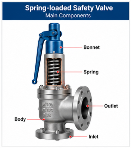
2. Understanding Required Capacity, Orifice Area and Rated Capacity
Three parameters are particularly important when reviewing a replacement safety valve: required relieving capacity, required discharge area and certified rated capacity.
| Parameter | Meaning | Engineering Importance |
|---|---|---|
| Required Relieving Capacity | Mass or volumetric flow that must be discharged during the governing relief scenario | Defines the required protection duty |
| Calculated Required Area | Minimum area determined using the applicable sizing method | Basis for preliminary orifice selection |
| Selected Orifice Area | Discharge area associated with the selected valve design | Must be assessed with the correct discharge coefficient |
| Certified Rated Capacity | Certified flow capability under specified conditions | Must be sufficient for the required duty after applicable corrections |
| Inlet and Outlet Sizes | Nominal connection dimensions of the valve | Affect piping compatibility and hydraulic performance |
Why Does a Larger Area Not Automatically Mean a Proportionally Larger Capacity?
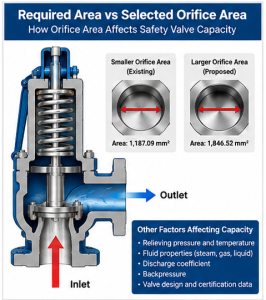
Discharge area is an important factor in valve capacity, but it is not the only factor.
The actual relieving capacity also depends on the upstream relieving pressure, fluid properties, temperature, discharge coefficient, applicable correction factors and valve construction.
For steam applications, API 520 Part I provides sizing methods based on mass flow, relieving pressure and factors associated with discharge performance and steam conditions.
In particular, the effective area used for preliminary API sizing must not be mixed with the certified discharge coefficient associated with a manufacturer’s actual valve area.
Final valve selection should use a consistent calculation basis and verify the selected valve’s certified capacity.
3. Engineering Case: Replacing a Steam Safety Valve
Consider an illustrative replacement project based on an industrial steam safety valve inquiry. The customer supplies an existing valve drawing and requests a replacement that maintains the original dimensional arrangement.
During technical evaluation, the engineering team reviews the specified relieving load and recalculates the discharge area.
| Technical Parameter | Project Information |
|---|---|
| Application | Steam pressure relief |
| Set Pressure | 4.8 MPa(g) |
| Specified Relieving Temperature | 264.5°C |
| Required Relieving Capacity | 27,572 kg/h |
| Calculated Required Area | 1,196.78 mm² |
| Area Shown on Existing Drawing | 1,187.09 mm² |
| Proposed Replacement Area | 1,846.52 mm² |
| Proposed Inlet | 4″ / DN100 |
| Proposed Outlet | 6″ / DN150 |
Engineering note: This is an illustrative technical clarification. The proposed area and dimensions are not a final certified sizing result. The steam state, relieving pressure, applicable code, area definitions and manufacturer-rated capacity must be verified before approval.
Step 1: Compare the Original Area with the Calculated Requirement
The customer’s existing drawing identifies an area of 1,187.09 mm², while the engineering review produces a calculated required area of 1,196.78 mm².
On a directly comparable area basis, the calculated requirement exceeds the drawing value by 9.69 mm², approximately 0.82%.
Although this difference appears small, the original arrangement should not automatically be accepted if it does not satisfy the applicable capacity verification.
However, the two values must first be confirmed as comparable. A manufacturer’s actual nozzle area and an API effective discharge area cannot be compared as if they were interchangeable.
Step 2: Evaluate the Next Suitable Valve Configuration
The engineering team proposes a replacement area of 1,846.52 mm².
This is approximately 54.3% larger than the calculated required area. It may represent the next suitable configuration available within the manufacturer’s valve range.
The difference does not mean the protected system requires 54.3% more relieving flow.
Instead, the proposed valve must be checked to confirm that its certified capacity, corrected for the specified relieving conditions, is at least equal to the required 27,572 kg/h.
Excessively oversized safety valves can also create operating concerns, including instability or cycling in some applications. Therefore, selecting the largest available orifice is not automatically the safest solution.
Step 3: Review the Inlet and Outlet Connections
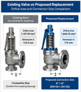
In this example, the larger proposed valve configuration is associated with a 4-inch inlet and 6-inch outlet.
The engineering recommendation may be necessary because the selected valve body and nozzle design require these connection sizes, or because the existing piping arrangement needs modification to satisfy hydraulic requirements.
Nevertheless, the nominal inlet and outlet sizes alone do not determine the internal orifice area or the certified discharge capacity.
The correct arrangement must be established using the manufacturer’s valve design and a review of the complete relief system.
4. Why Might the Inlet Size Need to Increase?
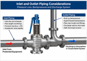
The inlet piping delivers pressurized fluid from the protected equipment to the safety valve.
If the inlet connection or upstream pipework is too restrictive, excessive pressure loss may occur while the valve is relieving.
For conventional spring-loaded valves, excessive non-recoverable inlet pressure loss can contribute to unstable operation or chatter.
API 520 Part II contains inlet piping requirements, including the commonly applied 3% inlet pressure-loss criterion for relevant installations. The exact requirements depend on valve type and application.
When reviewing an inlet size change, engineers should evaluate:
- The valve’s nominal inlet connection size.
- The protected equipment nozzle size.
- The inlet pipe internal diameter and schedule.
- The pipe length, fittings and reducers.
- The calculated pressure loss during relieving.
- The valve type and stability requirements.
If the selected replacement valve has a larger inlet than the original unit, the existing piping may also need modification. Installing a larger valve without reviewing the upstream piping is not a complete engineering solution.
5. Why Might the Outlet Size Need to Increase?
The discharge side of a safety valve carries the relieved fluid away from the valve, either to a suitable atmospheric discharge location or into a closed relief system.
During high-capacity steam relieving, the flow through the discharge piping can create significant backpressure.
Excessive backpressure may affect the opening behavior, stability and capacity of a pressure safety valve, depending on its design.
Therefore, changing the selected valve configuration may require the discharge piping to be reassessed.
Important checks include:
- Built-up and superimposed backpressure.
- Discharge pipe length, diameter and fittings.
- Valve-specific allowable backpressure.
- Discharge velocity and noise.
- Reaction forces and pipe supports.
- Thermal expansion and safe discharge location.
A larger outlet can reduce discharge restriction in some arrangements, but it does not eliminate the need for backpressure and discharge-system calculations.
6. How a Safety Valve Size Change Affects Installation Dimensions
For an existing plant, the physical installation is often one of the biggest challenges when engineers recommend changing the valve body size.
In the illustrative project, the original drawing includes a dimension A of 133.4 mm, while the proposed valve has a corresponding dimension of 179 mm.
| Installation Item | Existing Arrangement | Proposed Arrangement |
|---|---|---|
| Dimension A | 133.4 mm | 179 mm |
| Dimensional Change | — | +45.6 mm |
| Inlet / Outlet | Confirm against existing drawing | 4″ × 6″ |
| Flanges | Existing piping arrangement | Compatibility review required |
| Gaskets and Fasteners | Existing specification | May require replacement |
| Piping Supports | Existing arrangement | Reassessment may be necessary |
The proposed 45.6 mm dimensional difference may affect installation alignment, spool-piece lengths and available maintenance clearance.
Before manufacturing, the customer and supplier should confirm the exact dimension definition on both drawings.
If different flange sizes are required, new companion flanges, gaskets, bolts and nuts may also need to be procured.
Such changes can influence the total project cost and installation schedule even when the valve unit price is acceptable.
7. Can We Keep the Original Inlet and Outlet Sizes?
Many buyers prefer to retain the existing connection sizes because piping modifications can involve shutdown costs, fabrication work and additional approval procedures.
This request is reasonable, but it should be evaluated technically rather than accepted automatically.
An alternative valve may be suitable if another certified design can provide the required relieving capacity while meeting the existing connection and installation constraints.
However, a smaller replacement valve should not be approved solely because it fits the old pipeline.
The engineering team should verify:
- Required relieving duty and certified valve capacity.
- Manufacturer-specific orifice and nozzle configuration.
- Inlet piping pressure loss.
- Discharge backpressure and outlet piping suitability.
- Applicable pressure-temperature ratings.
- Valve stability and performance under the governing relief scenarios.
If no technically acceptable direct replacement is available, modification of the original piping arrangement may be necessary.
8. Safety Valve Replacement: Buyer and Engineer Approval Workflow
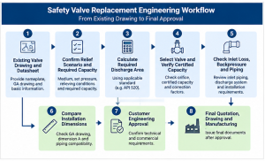
Existing Valve Drawing and Datasheet
↓
Confirm Relief Scenario and Required Capacity
↓
Calculate Required Discharge Area
↓
Select Valve and Verify Certified Capacity
↓
Check Inlet Loss, Backpressure and Piping
↓
Compare Installation Dimensions
↓
Customer Engineering Approval
↓
Final Quotation, Drawing and Manufacturing
This process helps ensure that the replacement valve is reviewed as part of the pressure-relief system rather than simply as an interchangeable mechanical component.
9. What Information Should Buyers Provide for a Replacement PSV Quote?
For accurate safety valve replacement sizing, the supplier needs more than the existing valve size and pressure class.
| Required Information | Examples or Details |
|---|---|
| Working Medium | Steam, gas, liquid or two-phase fluid |
| Required Capacity | kg/h, lb/h or applicable volumetric units |
| Pressure Data | Operating, set, relieving and backpressure |
| Temperature Data | Operating, design and relieving temperature |
| Existing Valve | Manufacturer, model, serial number and nameplate |
| Orifice Data | Area value, units and definition |
| Connections | Inlet/outlet size, flange class and facing |
| Materials | Body, disc, nozzle, spring and trim |
| Dimensions | GA drawing and installation-critical distances |
| Piping Information | Line sizes, schedules, lengths and discharge system |
| Standards | Applicable ASME, API, ISO or project requirements |
| Documentation | Capacity calculations, GA, certificates and test reports |
| Commercial Details | Quantity, destination, delivery requirement and Incoterms |
For projects involving customized valves, see our related article on replacement valve drawings and installation dimensions.
You can also review our pressure relief valves guide for additional information about relief-valve operating principles and basic selection considerations.
10. Relevant Standards for Safety Valve Replacement
The applicable standards depend on the protected equipment and project jurisdiction. Common references include:
- API 520 Part I: Sizing and selection of pressure-relieving devices within its scope.
- API 520 Part II: Installation requirements and guidance for pressure-relieving devices.
- API 526: Standardized flanged steel pressure-relief valve configurations.
- API 521: Assessment of pressure-relieving and depressuring systems.
- ASME BPVC Section VIII: Applicable pressure-vessel overpressure protection requirements.
- ASME BPVC Section I: Applicable power-boiler requirements where relevant.
- ISO 4126: Safety-device requirements where specified by the project.
These standards do not all apply to every installation. For example, power-boiler safety valves and pressure-vessel relief valves may fall under different code requirements.
Final compliance should be confirmed against the governing code and project specification.
11. Frequently Asked Questions
Why can a replacement safety valve require a larger orifice?
The existing valve may not have sufficient certified relieving capacity for the required overpressure scenario. After checking the calculated area, valve design and discharge coefficient, engineers may select a larger suitable orifice.
Does a larger orifice always require larger inlet and outlet connections?
No. Orifice area and nominal connection sizes are different parameters. A connection change may be necessary because of the selected valve design or piping requirements, but it is not an automatic consequence of increasing the orifice area.
Can the replacement valve use the original flange dimensions?
Yes, if a compatible certified valve design satisfies the required capacity, pressure loss, backpressure and installation requirements. Otherwise, piping and flange modifications may be necessary.
Why is the actual rated capacity different from a simple area calculation?
Rated capacity depends on the discharge area, certified discharge coefficient, relieving conditions, fluid properties and applicable corrections. Area alone is not sufficient to establish valve capacity.
Can a safety valve be oversized?
Yes. Excessive capacity relative to the relieving scenario can contribute to unstable operation in some installations. Engineers should select a suitable certified valve rather than automatically choosing the largest available orifice.
What should a buyer do when the manufacturer proposes a different inlet and outlet size?
Request the sizing calculation, certified capacity information and revised general arrangement drawing. The project engineer should review the inlet piping, discharge system, installation dimensions and applicable code requirements before approving the revised configuration.
12. Request a Safety Valve Replacement Engineering Review
When replacing an existing pressure safety valve, the original drawing is an important starting point, but the actual relieving requirements must determine whether the replacement design is acceptable.
Vcore Valve supports standard and customized industrial valve inquiries, including projects that require technical clarification, dimensional review and replacement valve quotations.
For a replacement PSV inquiry, please provide:
- Existing valve nameplate and GA drawing.
- Working medium and operating conditions.
- Set pressure and required relieving capacity.
- Relieving temperature and pressure.
- Existing inlet and outlet connection details.
- Required materials, standards and documentation.
- Project quantity and delivery destination.
Where a revised valve configuration is proposed, the technical differences should be reviewed and approved before an order is finalized.
Need assistance reviewing a replacement safety valve? Contact Vcore Valve to discuss your drawings, technical requirements and quotation.
Technical disclaimer: This article is intended for general engineering and procurement guidance. Safety valve sizing, selection, certification and installation must be verified by qualified personnel using the applicable codes, certified manufacturer data and complete process information.