
 Why Inclined Globe Valves Are Used in Process Plants
In many process facilities, engineers need a valve that can regulate flow gradually while still providing reliable shut-off when required. Traditional globe valves achieve good throttling performance but can introduce a significant pressure drop because of the sharp change in flow direction inside the valve body.
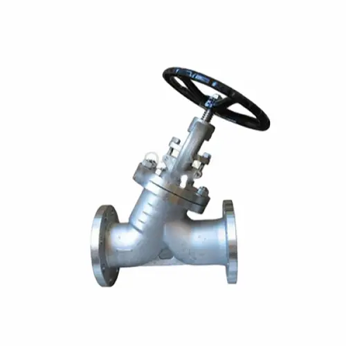
Vcore inclined globe valve modifies the internal flow path so that the fluid moves through the valve at a more gradual angle. This geometry reduces turbulence and hydraulic resistance.
In practical terms, operators often see the benefits in systems such as:
- refinery steam distribution headers
- chemical processing flow control lines
- power plant auxiliary steam circuits
- thermal oil transfer systems
In these environments, the valve may operate partially open for long periods while maintaining stable flow control.
Engineering Logic Behind the Inclined Flow Design
The defining feature of an inclined globe valve is the orientation of the seat and disc relative to the pipeline axis.
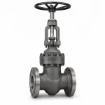
In a traditional T-pattern globe valve, fluid enters the valve body, turns sharply toward the seat, and then turns again to exit the valve. These abrupt changes in direction increase energy losses.
In contrast, the inclined configuration places the seat at an angle to the pipeline axis. The result is a smoother internal flow path.
This design typically leads to:
- higher flow coefficient (Cv)
- reduced pressure drop
- improved efficiency in throttling service
Because the disc moves in a straight vertical motion relative to the seat, the valve retains the precise throttling capability that globe valves are known for.
 Structural Features of the Valve
 Structural Features of the Valve
Bolted Bonnet Construction
The bolted bonnet joint is commonly used in industrial globe valves because it combines structural strength with ease of maintenance. The bonnet is attached to the body using bolting studs and sealed with a gasket.
During maintenance shutdowns, technicians can remove the bonnet assembly to access the internal components without removing the valve body from the pipeline.
Non-Rotating Rising Stem
Many inclined globe valves use a non-rotating stem configuration. In this arrangement, the stem moves vertically while the rotation occurs in the stem nut.
This design reduces wear on the packing set and helps maintain consistent sealing around the stem.
Body-Guided Disc
The valve disc is guided within the body cavity so that it remains properly aligned with the seat during operation. This guidance prevents uneven seating loads and helps maintain consistent sealing performance.
Hardfaced Seating Surfaces
Seating surfaces are often protected using hardfacing alloys such as cobalt-based overlays or hardened stainless steels. These materials provide resistance against erosion and repeated mechanical contact during throttling operation.
Typical Engineering Specifications
| Parameter | Specification |
|---|---|
| Valve Type | Low Pressure Bolted Bonnet Inclined Globe Valve |
| Nominal Size | NPS 2 – 18 (DN50 – DN450) |
| Pressure Rating | ASME Class 300 – 600 |
| Body Materials | ASTM A216 WCB, A351 CF8, CF8M |
| Trim Materials | 13Cr, SS304, SS316, Stellite Overlay |
| Seat Type | Metal Seated |
| End Connections | Flanged (ASME B16.5) |
| Stem Design | Non-Rotating Rising Stem |
| Disc Type | Body-Guided Disc |
| Temperature Range | –29°C to 425°C |
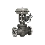
| Operation | Handwheel, Gear Operator, Electric Actuator |
Flow Performance and Pressure Drop Considerations
One of the main reasons engineers select inclined globe valves is improved hydraulic efficiency.
Flow through any valve introduces some degree of pressure loss. In globe valves this loss is largely determined by the internal flow path and the geometry of the seat opening.
Because the inclined design reduces abrupt directional changes, the valve typically offers a higher flow coefficient (Cv) than a conventional T-pattern globe valve of the same size.
In systems such as steam distribution pipelines, even a modest reduction in pressure drop can improve overall system efficiency.
For example, when regulating steam supply between process units, maintaining stable pressure while minimizing energy losses becomes an important operational consideration.
Typical Industrial Applications
Inclined globe valves appear in a variety of process industries where flow regulation is necessary but excessive pressure drop cannot be tolerated.
Common installations include:
- steam control lines in refineries
- boiler auxiliary systems in power plants
- chemical dosing and transfer pipelines
- thermal oil circulation systems
In these environments, operators often adjust valve opening positions gradually to maintain desired flow conditions.
Because the disc movement is linear and precise, globe valves remain one of the most reliable valve types for throttling service.

Maintenance Observations from Field Operation
From a maintenance standpoint, bolted bonnet globe valves are generally straightforward to inspect.
During scheduled plant shutdowns, technicians usually focus on three areas:
Seat condition
Frequent throttling can cause gradual wear on the seating surfaces. Hardfacing materials help extend service life in these conditions.
Stem packing integrity
Packing sets must maintain adequate compression to prevent leakage around the stem.
Stem threads and lubrication
Proper lubrication ensures smooth operation and prevents excessive wear on the stem nut.
Routine inspection of these components helps extend the service life of the valve and ensures reliable operation during plant startup cycles.
Selection Considerations for Engineers
Inclined globe valves are typically selected when the following conditions apply:
- moderate pressure service
- requirement for accurate flow regulation
- need to reduce pressure loss compared with traditional globe valves
However, if the application requires rapid on-off operation rather than throttling, other valve types such as ball valves or butterfly valves may be more appropriate.
Understanding the operating characteristics of each valve type helps engineers choose the most suitable equipment for the system.
FAQs
What is the advantage of an inclined globe valve compared with a standard globe valve?
The inclined design reduces pressure drop by creating a smoother internal flow path while maintaining precise throttling capability.
Are inclined globe valves suitable for throttling service?
Yes. Globe valves are widely used for flow regulation because the linear movement of the disc allows precise control of flow rate.
What industries typically use inclined globe valves?
They are commonly used in oil refining, chemical processing, power generation, and steam distribution systems.
Can inclined globe valves be automated?
Yes. They can be fitted with pneumatic or electric actuators for integration into automated control systems.