
 Where Floating Ball Valves Are Commonly Installed
In many industrial plants, valves are not operated continuously. A valve might remain open for weeks or even months until maintenance work requires a section of pipeline to be isolated. In these situations, engineers often prefer a valve design that provides reliable shut-off with minimal mechanical complexity.
Floating ball valves are frequently found in refinery utility pipelines, pump discharge lines, and tank transfer systems. These pipelines typically operate at moderate pressures and require dependable isolation during maintenance or operational switching. Because the sealing force increases with upstream pressure, the valve can maintain tight shut-off without complicated internal supports.
Another common installation environment is chemical storage facilities. When tanks are switched during loading or unloading operations, operators need a valve that closes quickly and seals reliably even after long idle periods. Floating ball valves are often selected for this purpose.
Engineering Logic Behind the Floating Ball Design
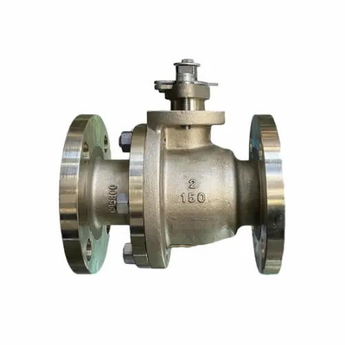
The key feature of a floating ball valve is the way the ball interacts with the valve seats. Instead of being fixed by trunnions, the ball is allowed to move slightly inside the valve body.
When the valve is open, the ball rotates freely with the stem and the bore aligns with the pipeline, allowing fluid to pass through the valve with relatively low resistance.
Once the valve is closed, upstream pressure pushes the ball toward the downstream seat. This movement increases the contact force between the ball and the seat material, forming the primary seal. The higher the upstream pressure, the stronger this sealing force becomes within the limits of the seat material.
This design works particularly well in medium-sized valves where the load on the seats remains manageable. As valve diameters increase significantly, the sealing load can become too high, which is why larger pipeline systems often use trunnion-mounted ball valves instead.
Typical Engineering Specifications
| Parameter | Typical Specification |
|---|---|
| Valve Type | Floating Ball Valve |
| Size Range | 1/2″ – 12″ (DN15 – DN300) |
| Pressure Rating | Class 150 – Class 600 |
| Body Materials | Carbon Steel (WCB), Stainless Steel (CF8, CF8M) |
| Ball Material | Stainless Steel 304 / 316 |
| Seat Materials | PTFE, Reinforced PTFE (RPTFE) |
| Stem Material | Stainless Steel |
| Connection Types | Flanged, Threaded, Butt Weld |
| Temperature Range | -20°C to 200°C |
| Operation | Lever, Gear Operated, Pneumatic Actuator, Electric Actuator |
| Applicable Media | Oil, Gas, Water, Chemical Fluids |
These specifications represent common configurations used in industrial pipeline systems. Actual designs may vary depending on the process conditions and project requirements.
 Material Selection in Different Industrial Environments
 Material Selection in Different Industrial Environments
Material selection for floating ball valves depends largely on the characteristics of the process fluid.
Carbon steel bodies are widely used in petroleum pipelines and industrial utility systems. These environments typically require strong pressure resistance and mechanical durability rather than extreme corrosion resistance.
In chemical processing facilities, stainless steel valves are often preferred because many process fluids can be corrosive. Stainless steel bodies provide better resistance to oxidation and chemical attack, which can extend valve service life.
The ball element is normally manufactured from stainless steel and polished to achieve a smooth sealing surface. Surface finish is important because the seat material must contact the ball evenly in order to maintain reliable shut-off performance.
Seat materials are typically PTFE or reinforced PTFE. These materials offer low friction during valve operation while maintaining stable sealing characteristics across a wide range of temperatures.
Maintenance Observations from Field Operation
From a maintenance perspective, floating ball valves are relatively straightforward to service. In most industrial facilities they are inspected during scheduled shutdown periods.
Two components are usually examined first.
Seat rings are checked for signs of wear or deformation. Because pipeline pressure pushes the ball against the downstream seat during closure, that seat may experience higher loads over time. In systems carrying abrasive particles, this area may also show erosion.
Stem packing is another area that may require adjustment. Temperature fluctuations and repeated operation can gradually reduce packing compression, which may lead to minor leakage around the stem. Tightening the packing gland normally restores proper sealing.
Because floating ball valves contain fewer internal structural components than some other valve designs, maintenance work is generally straightforward.
 Valve Selection Considerations
 Valve Selection Considerations
Floating ball valves are typically selected when pipeline conditions fall within certain practical limits.
They are often recommended when the pipeline diameter is below approximately 12 inches and the pressure rating does not exceed Class 600. Under these conditions, the floating ball mechanism can provide reliable sealing without excessive operating torque.
For larger pipeline diameters or significantly higher pressures, trunnion-mounted ball valves may be more suitable. In those designs the ball is supported by mechanical shafts that reduce the load placed on the seat rings.
Understanding these limits helps engineers select the most appropriate valve type for each pipeline section.
Common Selection Mistakes
One common mistake occurs when floating ball valves are installed in large-diameter pipelines operating at relatively high pressure.
As valve size increases, the force pushing the ball against the seat becomes much greater. This can lead to higher operating torque and increased seat wear. In such cases, engineers often switch to trunnion-mounted ball valves, which distribute mechanical loads more effectively.
Another issue sometimes arises when floating ball valves are used for continuous throttling. These valves are primarily designed for full-open or full-closed service rather than precise flow regulation.
FAQs
What is the main difference between floating ball valves and trunnion ball valves
Floating ball valves rely on pipeline pressure to push the ball against the downstream seat for sealing. Trunnion ball valves use mechanical supports that hold the ball in position, reducing seat load in larger or higher-pressure systems.
What size range is typical for floating ball valves
Floating ball valves are commonly used in pipelines ranging from 1/2 inch to around 12 inches in diameter.
Can floating ball valves be automated
Yes. Floating ball valves can be equipped with pneumatic or electric actuators for automated operation in industrial systems.
Are floating ball valves suitable for flow regulation
They are primarily intended for isolation service rather than continuous throttling.