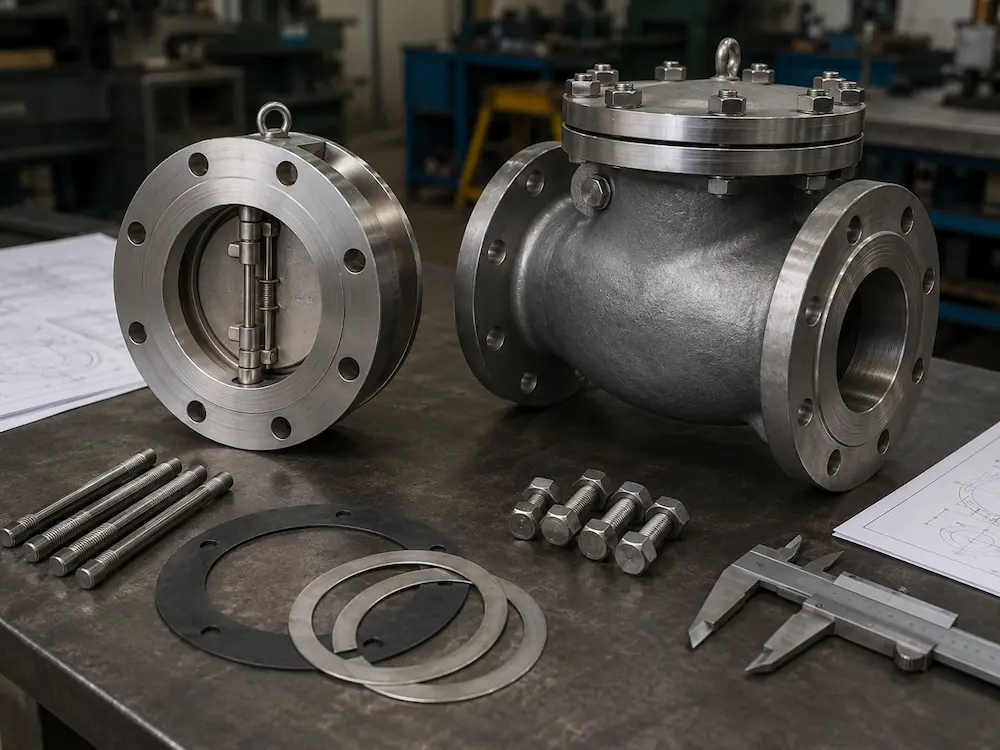
Wafer check valve vs flanged check valve selection is an important decision in industrial pipeline design. Both valve types prevent reverse flow automatically, but their installation methods, face-to-face length, body weight, flange bolting, maintenance access, and application suitability are different.
A wafer check valve is installed between two pipeline flanges. It usually has a compact body and short face-to-face dimension. A flanged check valve has its own flanged ends and is bolted directly to mating pipe flanges. This makes the valve heavier and longer, but often easier to install, align, remove, and maintain as an independent pipeline component.
For B2B buyers, the correct choice depends on pipeline layout, available installation space, pipe support, pressure class, valve size, maintenance plan, medium, flow condition, water hammer risk, and project standard. For a broader overview of check valve types and selection logic, read our main guide on industrial check valves.
What Is a Wafer Check Valve?
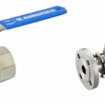
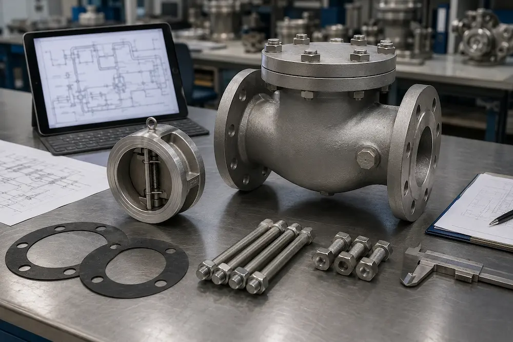
A wafer check valve is a compact check valve installed between two pipe flanges. Instead of having full flanged ends on the valve body, the wafer body is clamped between the pipeline flanges using long bolts or studs.
Wafer check valves are widely used where installation space, valve weight, and compact pipeline design are important. They are common in water treatment, HVAC, marine systems, pump discharge lines, process skids, fire protection, and general industrial utility pipelines.
Common wafer check valve designs include dual plate wafer check valves, wafer lift check valves, and wafer swing check valves. Buyers may review a wafer lift type check valve or wafer swing type check valve depending on flow direction, pressure, medium, and installation requirements.
Key Features of Wafer Check Valves
- Compact body design
- Short face-to-face dimension
- Installed between two pipe flanges
- Usually lighter than flanged check valves
- Useful for space-limited piping systems
- Requires correct flange alignment and bolt tightening
- Maintenance usually requires loosening adjacent flange connections
What Is a Flanged Check Valve?
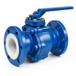
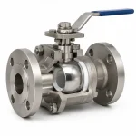
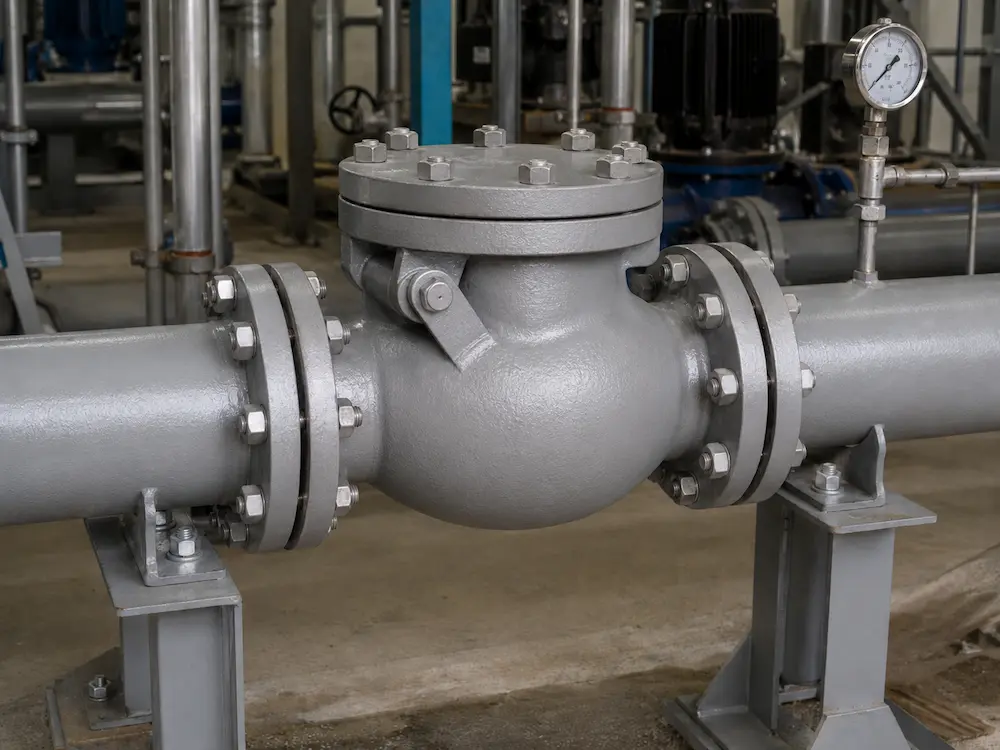
A flanged check valve has integral flanged ends on the valve body. The valve is installed by bolting each valve flange to the corresponding pipe flange. This design provides stronger body support and a more conventional installation method for many industrial pipelines.
Flanged check valves are commonly used in water systems, wastewater plants, oil and gas pipelines, chemical processing, power plants, steam utilities, pump stations, and general industrial service. They are often selected when pipeline size is larger, pressure class is higher, maintenance access is important, or the project specification requires standard flanged construction.
Key Features of Flanged Check Valves
- Integral flanged ends on the valve body
- Longer face-to-face dimension than most wafer designs
- Heavier and more robust body structure
- Independent bolted connection at both ends
- Easier removal and maintenance compared with many wafer installations
- Common in larger pipelines and conventional industrial piping
- Requires more installation space and stronger pipe support
Wafer Check Valve vs Flanged Check Valve: Core Difference Table
| Comparison Factor | Wafer Check Valve | Flanged Check Valve |
|---|---|---|
| Connection Method | Clamped between two pipe flanges using through bolts or studs | Bolted directly to pipe flanges through integral valve flanges |
| Face-to-Face Length | Short and compact | Longer than wafer design |
| Weight | Usually lighter | Usually heavier |
| Installation Space | Better for limited space | Requires more piping space |
| Pipe Support Requirement | Lower valve weight, but flange alignment is critical | Higher weight may require stronger support |
| Maintenance Access | May require loosening adjacent flange bolts | Often easier to isolate and remove as a separate component |
| Typical Use | Compact systems, HVAC, water treatment, pump discharge, skids | Large pipelines, heavy-duty service, conventional plant piping |
| Main Buyer Risk | Incorrect bolting, flange misalignment, gasket compression issues | Higher weight, larger space requirement, higher material cost |
Installation Difference
The biggest practical difference between wafer and flanged check valves is installation. A wafer check valve is placed between two existing pipe flanges. The pipeline bolts pass through the flange holes and clamp the valve body in position. The valve does not have separate full flanged ends.
A flanged check valve is installed as a complete flanged valve assembly. Each end of the valve has a flange, and each valve flange is bolted to the corresponding pipeline flange. This makes the installation more familiar for many piping teams and easier to handle as an independent valve unit.
Wafer Check Valve Installation Notes
- Flange alignment must be accurate
- Gaskets must be correctly positioned on both sides
- Bolts or studs must be tightened evenly
- The valve must be centered between flanges
- Flow direction must match the valve marking or drawing
- Maintenance may require disturbing both adjacent flange joints
Flanged Check Valve Installation Notes
- Valve flanges must match the pipeline flange standard
- Gasket type and flange face must be compatible
- Pipe supports should carry valve weight properly
- Enough space should be reserved for installation and removal
- Bolting and torque sequence should follow project requirements
- Flow direction must be confirmed before installation
Space and Weight Comparison
Wafer check valves are usually chosen when installation space is limited. Their compact face-to-face dimension makes them useful in pump rooms, HVAC systems, water treatment skids, marine systems, retrofit projects, and compact utility pipelines.
Flanged check valves require more space because the valve body includes full flanged ends. They are also heavier, especially in larger sizes. However, this heavier structure may be preferred in conventional process piping where robustness, independent installation, and maintenance access are more important than compact size.
When Compact Design Matters
- Existing pipeline space cannot be extended
- Process skid layout is compact
- Valve weight affects support design
- Equipment rooms have limited installation clearance
- Large numbers of valves must be installed in limited space
Pressure Class and Structural Support
Both wafer and flanged check valves can be designed for industrial pressure classes, but the correct choice depends on valve design, material, flange standard, gasket arrangement, and project requirements.
A wafer check valve depends heavily on the surrounding pipe flanges for clamping and sealing. This makes flange alignment, bolt length, gasket placement, and tightening sequence very important. If installation is poor, leakage or uneven body stress may occur.
A flanged check valve has a more complete pressure-containing body with integral end flanges. It is often preferred in heavier-duty service, larger pipelines, higher structural loads, or applications where the project specification requires flanged-end valve construction.
Buyers should not assume that wafer always means low pressure or flanged always means high pressure. The pressure rating must be confirmed by valve standard, body material, design, and test documentation.
Maintenance and Replacement
Maintenance access is another important difference. A wafer check valve saves space and weight, but removal usually requires loosening the adjacent pipeline flanges. This can be inconvenient if the valve is installed in a tight area or if flange alignment is difficult to restore after maintenance.
A flanged check valve is often easier to remove as a complete valve assembly because it has its own flanged ends. Maintenance teams can isolate the valve, remove flange bolts at both ends, and lift out the valve if enough space and support are available.
Maintenance Factors to Review
- Can the pipeline be drained and depressurized easily?
- Is there enough space to remove the valve?
- Can flange alignment be maintained after removal?
- Are gaskets and bolts easy to replace?
- Can internal parts such as disc, plate, hinge, spring, or seat be inspected?
- Is the valve located in a high-maintenance or critical service area?
Pressure Drop and Flow Behavior
Pressure drop depends more on internal valve design than connection style alone. A wafer check valve can be a dual plate, lift, or swing design. A flanged check valve can also be swing, lift, piston, or other structure. Therefore, buyers should compare the actual valve type and flow coefficient, not only the connection method.
For example, a wafer dual plate check valve may close faster and save space, but the plates and spring mechanism create their own flow behavior. A flanged swing check valve may provide low pressure drop in steady flow, but it may require more space and may close more slowly in some pump discharge systems.
The correct selection should consider flow rate, minimum flow velocity, pressure drop limit, valve type, and water hammer risk together.
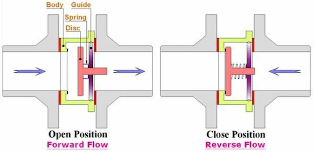
Water Hammer and Closing Behavior
Water hammer risk is not determined only by wafer or flanged connection. It depends on how fast the closure element closes, how much reverse flow develops, pump shutdown behavior, pipeline length, flow velocity, and system pressure.
Many wafer check valves, especially dual plate designs, use spring-assisted closure and can close faster than traditional swing check valves. This may help reduce reverse flow before closure. However, a poorly selected wafer valve can still chatter, slam, or create pressure loss.
Flanged swing check valves are widely used, but in pump discharge systems with rapid flow reversal, the disc may close late and slam. In severe water hammer applications, buyers should review dual plate, spring, nozzle, or non-slam check valve options.
For more details on swing and spring closing behavior, read our guide on swing check valve vs spring check valve.
Application Comparison
| Application | Recommended Direction | Reason |
|---|---|---|
| Compact pump room | Wafer check valve | Short face-to-face dimension saves installation space |
| Large conventional process pipeline | Flanged check valve | Robust body and easier independent removal may be preferred |
| HVAC system | Wafer check valve | Compact and lighter design is often useful |
| Water treatment skid | Wafer or flanged check valve | Selection depends on space, pressure, maintenance, and flow condition |
| High-maintenance service | Often flanged check valve | Easier removal and inspection may be valuable |
| Retrofit project with limited pipe gap | Wafer check valve | Compact body may fit existing space more easily |
| High water hammer risk | Depends on closure design | Review dual plate, spring, nozzle, or non-slam options |
Material and Seat Selection
Wafer and flanged check valves can be supplied in different materials. The correct material depends on medium, pressure, temperature, corrosion risk, and project standard. Buyers should review not only the body material, but also the disc, plate, spring, hinge pin, seat, gasket, and bolting material.
| Component | Common Options | Buyer Notes |
|---|---|---|
| Body | Cast iron, ductile iron, carbon steel, stainless steel, alloy | Select according to pressure, corrosion risk, and project standard |
| Disc / Plate | Stainless steel, ductile iron, carbon steel, bronze, coated materials | Must resist corrosion, impact, and wear |
| Spring / Hinge | Stainless steel, alloy spring, corrosion-resistant material | Important for wafer dual plate, spring, and compact designs |
| Seat | Metal, EPDM, NBR, FKM, PTFE | Affects leakage performance, temperature, and medium compatibility |
| Gasket | Rubber, PTFE, graphite, spiral wound, project-specified material | Must match flange face, pressure, temperature, and chemical service |
| Bolting | Carbon steel, stainless steel, alloy bolting | Must match flange standard, corrosion environment, and tightening requirements |
Common Selection Mistakes
Mistake 1: Choosing Wafer Valves Only Because They Are Compact
Wafer check valves save space, but they require correct flange alignment, gasket seating, and bolt tightening. If the installation is poor, leakage or uneven compression can occur.
Mistake 2: Choosing Flanged Valves Without Checking Space
Flanged check valves are robust, but they require more installation space and may be heavier. In compact pump rooms or process skids, the longer body may create layout problems.
Mistake 3: Confusing Connection Type with Valve Type
Wafer and flanged describe connection style. Swing, lift, dual plate, piston, and nozzle describe internal check valve structure. A complete specification should include both connection and internal valve type.
Mistake 4: Ignoring Bolt Length and Gasket Requirements
Wafer valves often require specific bolt lengths and proper gasket placement. Incorrect bolts or gasket compression can cause leakage or installation failure.
Mistake 5: Ignoring Maintenance Access
A compact valve may be difficult to remove if installed in a tight area. Maintenance access should be reviewed before selecting wafer or flanged construction.
Mistake 6: Assuming Pressure Rating Without Documentation
Pressure class should be confirmed by valve design, material, flange standard, and test report. Do not rely only on appearance or connection type.
How to Choose Between Wafer and Flanged Check Valves
| Selection Question | If Yes | Likely Direction |
|---|---|---|
| Is installation space limited? | Short face-to-face length is important. | Wafer check valve |
| Is valve weight a concern? | Pipe support load should be reduced. | Wafer check valve |
| Is independent removal important? | Maintenance access is a priority. | Flanged check valve |
| Is the pipeline large and heavy-duty? | Robust body support is preferred. | Often flanged check valve |
| Is the project a retrofit? | Existing pipe gap is limited. | Often wafer check valve |
| Is flange alignment difficult? | Uneven compression may be a risk. | Flanged design may be easier to control |
| Is water hammer a major concern? | Closing speed must be reviewed. | Select by internal valve type, not connection alone |
Information Buyers Should Provide Before Quotation
- Valve size and pipeline size
- Required connection type: wafer, lug, or flanged
- Flange standard and pressure class
- Face-to-face dimension requirement if space is limited
- Medium name and composition
- Operating pressure and design pressure
- Operating temperature and maximum temperature
- Normal, minimum, and maximum flow rate
- Installation direction: horizontal, vertical upward, or vertical downward
- Application: pump discharge, HVAC, water treatment, chemical, gas, oil, wastewater, or marine
- Water hammer or non-slam requirement
- Body, disc, plate, spring, seat, gasket, and bolting material requirements
- Required drawings, test reports, certificates, and documentation
Related Check Valve Guides
For broader check valve selection and installation details, these related guides may help:
- Industrial Check Valves: Types, Applications and Selection Guide — main guide for check valve types, backflow prevention, materials, and selection logic.
- Dual Plate Check Valve vs Swing Check Valve — compares compact dual plate design with traditional swing check structure.
- Swing Check Valve vs Spring Check Valve — compares hinged disc closure and spring-assisted closure for industrial pipelines.
- Can a Check Valve Be Installed Vertically? — explains vertical installation, flow direction, and check valve type suitability.
- Check Valve Product Range — compare wafer, swing, lift, dual plate, nozzle, and other industrial check valve options.
Final Recommendations for Industrial Buyers
A wafer check valve is usually a good choice when installation space is limited, valve weight must be reduced, or a compact between-flange design is preferred. It is commonly used in HVAC, water treatment, process skids, pump rooms, marine systems, and retrofit projects.
A flanged check valve is usually preferred when a more robust independent valve body is required, maintenance access is important, or the pipeline layout has enough space for a longer and heavier valve. It is widely used in conventional industrial piping, pump stations, water systems, chemical processing, power plants, and oil and gas service.
If you need help choosing between wafer check valves and flanged check valves for pump discharge, water treatment, chemical processing, HVAC, marine, oil and gas, wastewater, or industrial utility service, Vcore Valve can review your working conditions and recommend a suitable check valve configuration. Buyers can also compare available options in our check valve category.
For industrial sourcing, the key question is not only “wafer or flanged?” The better question is: “Which connection style, internal check valve design, material, pressure class, and maintenance arrangement fit this exact pipeline system?”
FAQ
1. What is the difference between a wafer check valve and a flanged check valve?
A wafer check valve is clamped between two pipe flanges using long bolts or studs. A flanged check valve has integral flanged ends and is bolted directly to the pipeline flanges as an independent valve body.
2. When should I choose a wafer check valve?
Choose a wafer check valve when installation space is limited, valve weight matters, and a compact between-flange design is suitable for the pressure, flow, and maintenance requirements.
3. When should I choose a flanged check valve?
Choose a flanged check valve when robust construction, easier independent removal, conventional piping layout, or stronger support is required.
4. Is a wafer check valve suitable for high pressure?
It depends on valve design, material, flange standard, gasket arrangement, and test documentation. Wafer construction alone does not define pressure suitability.
5. Which valve is easier to maintain?
A flanged check valve is often easier to remove as a separate valve assembly. A wafer check valve is compact, but removal may require loosening adjacent pipeline flanges.