Quick Overview
There is no universal minimum air pressure for a pneumatic valve. Before ordering, specify the minimum, normal and maximum supply pressures, the measurement point, and the pressure available during valve movement. Actuator selection must account for valve torque or thrust, process differential pressure, spring configuration and accessory losses. Confirm the required behaviour on loss of air, electrical power and control signal separately.
A pneumatic valve may complete its stroke during a workshop check yet move slowly or stop before reaching its end position after installation. One possible cause is a difference between the air pressure used for actuator selection and the pressure actually available during operation.
An enquiry stating only “air supply: 6 bar” leaves several questions unanswered. Is that the normal header pressure, the regulator setting, or the minimum pressure available at the valve package whilst it is moving?
This guide explains what buyers should specify about pneumatic valve minimum air pressure before ordering an automated valve or replacement actuator.
What Does Minimum Air Pressure Mean?
Two different values must be distinguished: the minimum pressure required by the valve assembly and the minimum pressure available from the site.
- Minimum required pressure: the pressure needed for the selected assembly to deliver the required movement, seating performance and operating time under defined conditions.
- Minimum available pressure: the lowest supply pressure the site can provide at an agreed connection point during the specified operating conditions.
The available supply must support the assembly’s requirements after accounting for the pneumatic circuit. A pressure stated at the plant header cannot automatically be treated as the pressure delivered to the actuator chamber.
All pressure values should identify their units and reference. For example, “barg” means gauge pressure; it should not be confused with absolute pressure.
1. Specify Minimum, Normal and Maximum Supply Pressure
Normal supply pressure describes a typical operating condition. Minimum pressure is a key sizing input, whilst maximum pressure is needed to check component limits and possible mechanical overload.
| Pressure Item | Purpose | What to State |
|---|---|---|
| Minimum available supply pressure | Establishes the lowest specified pneumatic supply condition for selection | Value, units, measurement point and whether it applies during movement |
| Normal supply pressure | Describes typical operation and supports air-demand assessment | Expected pressure at the same defined connection point |
| Maximum available supply pressure | Supports component-rating and overload checks | Highest credible pressure, including relevant regulator or supply conditions |
| Regulated package supply | Defines the intended pressure delivered downstream of the regulator | Setting, permitted variation and performance at the required flow |
| Actuator chamber pressure | Produces force or torque during the stroke | Pressure conditions used in the actuator calculation, including exhaust-side effects where relevant |
For example, a plant may normally operate at 6 barg but guarantee only 4.5 barg at the package inlet during simultaneous demand. Selection based solely on 6 barg could overestimate the available output. These figures are illustrative and do not represent a standard Vcore operating range.
2. Define Where Pressure Is Measured
Identify the connection point on the pneumatic schematic. Common locations include the plant header, the valve package inlet, the filter-regulator outlet and the actuator ports.
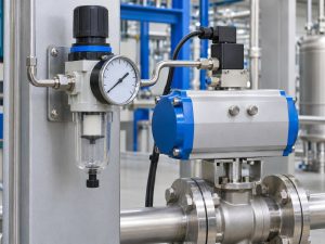
Between the header and actuator, air may pass through isolation valves, tubing, filters, regulators, solenoid valves, positioners and flow controls. Each can influence the pressure and flow available during movement.
Static Pressure Is Not Dynamic Pressure
A gauge may show the expected pressure whilst the actuator is stationary. When the valve moves, air flows through the supply circuit and pressure can fall across restrictions.
Ask for the minimum pressure available during the relevant operating sequence, including simultaneous operation of other air consumers where applicable. A single gauge reading taken with no air demand is not sufficient to establish that condition.
Allocate Pressure Losses Once
If the site guarantees pressure at the package inlet, the supplier should account for the losses through the supplied accessories. If a guaranteed value already applies at another downstream point, identify that point clearly so the same allowance is not deducted twice.
Air volume and peak demand also affect the supply arrangement. See the pneumatic actuator air consumption guide when reviewing cycle frequency and shared air demand.
3. Match Actuator Output to Valve Load
Minimum air pressure cannot be selected independently of the valve. The actuator must overcome the required torque or thrust throughout the specified travel under the governing process conditions.
Quarter-Turn Ball and Butterfly Valves
For quarter-turn valves, compare the actuator output curve with the valve’s opening, running, closing and seating torque requirements. Relevant factors include:
- Maximum operating and shut-off differential pressure.
- Seat construction, packing friction and service temperature.
- Medium characteristics, deposits and prolonged idle periods.
- Required operating direction and stroke time.
- The agreed sizing allowance and mechanical limits.
A catalogue torque quoted at one supply pressure or one angular position does not establish suitability for the complete stroke. The valve actuator torque sizing guide explains the relationship between valve demand, actuator output and maximum allowable stem torque.
Linear Control Valves
For a sliding-stem control valve, selection requires a thrust assessment. Process unbalance, packing friction, seating force, spring force and available pneumatic pressure must be evaluated for the selected travel and action.
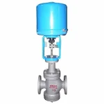
For a pneumatic diaphragm control valve, provide the required shut-off differential pressure, leakage acceptance criteria, air supply and fail position. The actuator and positioner configuration must be confirmed for the offered assembly.
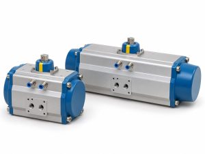
4. Distinguish Double-Acting and Spring-Return Requirements
| Actuator Arrangement | Minimum-Pressure Review | Limitations to Confirm |
|---|---|---|
| Double-acting | Check pneumatic output in both directions throughout travel | Include pressure on the exhaust side where relevant; air failure does not automatically establish a holding position |
| Spring-return | Check the air-powered stroke against valve load and spring resistance | Verify spring output throughout the return stroke and confirm that the circuit permits the required exhaust |
| Engineered stored-air arrangement | Check usable stored air and pressure for the required emergency sequence | Receiver sizing, leakage allowance, accessories and available reserve require a specific calculation |
For spring-return assemblies, confirming that air pressure can compress the springs is only part of the review. The springs must also provide sufficient output to complete the required return movement against the valve load.
Do not apply a universal pressure threshold to all spring-return actuators. Spring set, actuator size, valve demand and operating conditions determine the required supply.
5. Specify Failure Behaviour for Each Event
“Normally closed” does not fully describe how an automated valve should respond to failures. Define the required valve position and response time for each relevant event.
- Loss of instrument air.
- Loss of electrical power to the solenoid or positioner.
- Loss of the control signal.
- A commanded emergency shutdown.
These events may produce different results because the pneumatic circuit can vent, trap or redirect air. A double-acting actuator should not be described as fail-in-place without an assessment of process forces, leakage and the complete holding arrangement.
Likewise, a spring-return actuator reaches its intended fail position only when its spring output and pneumatic circuit are suitable for the required duty. Trapped pressure or a restricted exhaust can affect that response.
Field Insight: Put the Air-Supply Boundary in the Vcore Enquiry
When requesting a pneumatic valve quotation from Vcore Valve, state where the site air supply ends and the supplied valve package begins. This makes responsibility for tubing, filtration, regulation and accessory pressure losses clearer.
What to Check:
- What minimum dynamic pressure is guaranteed at the package inlet?
- Which regulator, solenoid, positioner and tubing are included in the quotation?
- What process differential pressure governs actuator selection?
- What movement is required after loss of air, power or signal?
Ask for the quotation, actuator calculation and pneumatic schematic to use the same pressure boundary and operating cases. If the site minimum is unknown, identify it as an assumption requiring confirmation before the actuator is finalised.
6. Review Accessories, Air Quality and Stroke Time
An actuator can have adequate theoretical output but still miss the required stroke time if the supply or exhaust circuit cannot pass sufficient air.
Regulators, Solenoids and Tubing
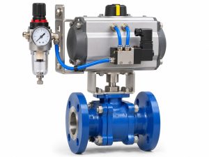
Review regulator flow performance, solenoid capacity, tubing internal diameter and length, fittings, speed controls and exhaust silencers. A port thread size alone does not establish the available flow capacity.
Pilot-operated accessories may also have their own minimum operating pressure or differential-pressure requirement. Confirm those limits for the selected models rather than assuming that an accessory will operate whenever the actuator can move.
For a pneumatic soft-seated butterfly valve package, the valve, actuator and accessories should be reviewed together against the air supply, torque and response-time requirements.
Positioner Supply Is Different from Signal Range
A 3–15 psi pneumatic signal normally describes a command range, not the available actuator supply. Similarly, a 4–20 mA electrical signal does not provide the pneumatic energy required to move the valve.
Specify the positioner’s supply conditions separately and allow for its output capability and pressure requirements. Calibration cannot compensate for inadequate actuator output or a restricted air supply. See the control valve positioner calibration guide for the checks that should precede calibration.
Air Quality and Temperature
Specify the required instrument-air quality for the selected equipment and site conditions. Where an ISO 8573-1 classification is required, state the agreed particle, water and oil classes rather than writing only “clean air”.
The required pressure dew point should account for the lowest expected exposure temperature. Filtration, drainage, elastomer compatibility and any lubrication requirements must follow the selected component instructions. Do not add a lubricator by default.
7. Check Maximum Pressure as Well as Minimum Pressure
Raising pressure can increase actuator output, but it is not an automatic remedy for an undersized assembly. Maximum supply conditions must remain within the limits of the actuator, positioner, solenoid, regulator, tubing and other affected components.
The review must also consider the valve stem, shaft, coupling, mounting bracket and permissible seating loads. A larger actuator selected for low-pressure operation can produce excessive output if later exposed to a higher pressure.
Confirm the regulator setting and any required pressure-limiting or protective measures as part of the approved design.
What to Include in the RFQ
| RFQ Item | Information Required |
|---|---|
| Valve duty | Valve type, size, pressure rating, materials and on-off or modulating operation |
| Process conditions | Medium, temperatures, upstream and downstream pressures, and governing shut-off differential pressure |
| Air supply | Minimum, normal and maximum pressures with units and a defined connection point |
| Dynamic conditions | Guaranteed pressure during movement, simultaneous demand and relevant supply limitations |
| Actuator action | Double-acting or spring-return, with required fail behaviour for each specified event |
| Operating time | Opening and closing time limits, cycle frequency and emergency stroke requirements |
| Accessories | Regulator, solenoid, positioner, switches, flow controls, manual override and package tubing scope |
| Environment | Ambient temperature, air quality, corrosion exposure and any applicable hazardous-area requirements |
| Verification | Sizing calculation, pneumatic schematic, test conditions and required records |
Suggested Purchase Specification
The supplier shall select the pneumatic valve assembly using the specified minimum dynamic air pressure at the agreed package supply connection. The assessment shall account for pressure losses through the supplied pneumatic accessories and verify actuator torque or thrust throughout the required travel under the governing process conditions. Maximum supply conditions shall be checked against component ratings and mechanical load limits. Required responses to loss of air, electrical power and control signal shall be stated separately. Any unconfirmed site conditions or sizing assumptions shall be identified in the quotation.
Verification Before Shipment and During Commissioning
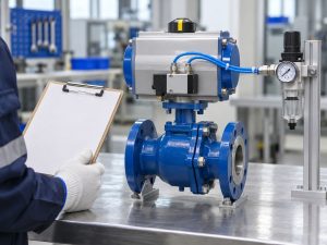
Agree the acceptance procedure before testing. Where required by the order, verify operation at the specified minimum supply pressure using the final accessory arrangement and record pressure at the agreed measurement point.
- Confirm full travel and correct position indication.
- Record opening and closing times under the stated test conditions.
- Check the specified fail actions and recovery sequence.
- Verify regulator settings and relevant pressure limits.
- State whether process load was applied, simulated or assessed by calculation.
An unloaded workshop stroke does not prove shut-off capability at the maximum process differential pressure. Keep functional checks, loaded performance verification and seat leakage testing clearly identified in the inspection scope.
During commissioning, check pressure whilst the valve moves and whilst other relevant air consumers operate. Investigate restrictions, leakage and exhaust conditions if the installed response differs from the approved basis.
Frequently Asked Questions
What is the minimum air pressure for a pneumatic valve?
There is no universal value. The required pressure depends on valve torque or thrust, actuator size, spring configuration, process conditions and accessory losses. Confirm the minimum dynamic supply pressure at the agreed package connection and verify the actuator output under the corresponding conditions.
Is a normal plant air pressure of 6 barg enough for actuator selection?
Not by itself. Provide minimum, normal and maximum pressures, identify where they apply, and include pressure reductions during valve movement and simultaneous air demand.
Does a 3–15 psi signal specify the actuator supply pressure?
No. It normally describes a pneumatic control signal range. The positioner supply pressure and actuator operating pressure must be specified separately.
Will a double-acting actuator stay in position after air failure?
Not necessarily. Position after air failure depends on process forces, leakage and the pneumatic circuit. Specify any required holding or emergency action and obtain confirmation for the complete assembly.
Can increasing the regulator setting solve low actuator output?
Only if the revised setting remains within every affected component’s approved limits and the valve, stem, coupling and actuator have been checked. Increasing pressure without review can overload the assembly.
Should minimum-air-pressure testing be included in the order?
Yes, when it is part of the project acceptance requirements. Define the pressure measurement point, accessories, process load or agreed simulation, stroke-time limits and fail-action checks before testing. An unloaded workshop stroke alone does not prove performance at the required process differential pressure.
Prepare Your Pneumatic Valve Enquiry for Vcore Valve
Send Vcore Valve the valve duty, process conditions, minimum available dynamic air pressure and required failure behaviour. Include the package connection point and accessory scope so the quotation can identify a consistent selection basis.
If the minimum site pressure has not been confirmed, state that clearly. Any proposed actuator configuration should identify the assumption used and the information needed before final technical approval.