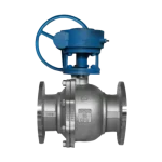
Quick Summary: Valve actuator torque sizing should compare actuator output with valve torque demand throughout the full opening and closing stroke, not only one catalogue torque value. Buyers should check break-to-open torque, running torque, break-to-close torque, seating torque, maximum differential pressure, minimum air pressure or worst electrical supply condition, safety factor and maximum allowable stem torque. A pneumatic actuator must be checked at the minimum available air pressure at the actuator, and a spring-return actuator must be checked on both the air stroke and spring stroke. An oversized actuator is not automatically safer because excessive output can damage the valve stem, gearbox, coupling or mounting interface. Final sizing should use verified valve manufacturer torque data, documented service assumptions and approved project margins.
An actuator can look large enough on a catalogue page and still fail to move the valve in service. The usual reason is not a lack of nominal actuator torque. It is a mismatch between the valve’s changing torque demand and the actuator’s changing output during the stroke.
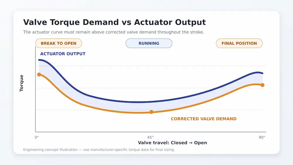
A quarter-turn valve may need its highest torque when it first moves away from the closed seat. It may need less torque through mid-travel, then require another increase to reach the specified closed position. A pneumatic spring-return actuator produces different output on its air and spring strokes. An electric actuator may have separate rated, starting, seating and maximum output limits. Comparing one valve number with one actuator number therefore does not establish a reliable sizing result.
This guide explains a practical valve actuator torque sizing method for industrial ball, butterfly and plug valves. It also shows where safety factors belong, why minimum air pressure or low supply voltage matters, and how maximum allowable stem torque can disqualify an actuator that appears powerful enough.
Quick Torque Sizing Check
| Sizing Point | What to Check | Why It Matters |
|---|---|---|
| Break-to-open torque | Torque required to move the valve from the closed position. | Often one of the highest torque points, especially for seated quarter-turn valves. |
| Running torque | Torque during valve travel. | May change with valve type, pressure, flow condition, packing friction and deposits. |
| End-to-close / seating torque | Torque needed to reach the final closed position. | Too little torque can cause leakage; too much can damage the seat, stem or coupling. |
| Minimum actuator output | Output at the worst available air pressure or electrical supply condition. | Catalogue output may not match the real site condition at the actuator. |
| Maximum actuator output | Highest possible actuator output or torque-switch setting. | Must remain below MAST, gearbox, coupling, drive and mounting limits. |
| Safety factor | Project-approved margin applied to verified valve torque data. | Adds allowance for real service without replacing the service review. |
What Valve Actuator Torque Sizing Must Prove
A complete sizing check must prove four things:
- The actuator can start the valve moving from either end position when required.
- The actuator can continue through the full stroke without a torque deficit.
- The actuator can reach the required final position and achieve the specified shutoff condition.
- The actuator’s maximum possible output will not damage the valve stem, drive train, gearbox, coupling or mounting components.
The first three checks establish minimum required output. The fourth establishes the maximum acceptable output. Good sizing must fit inside both boundaries.
The result also has to remain valid under the real power conditions. Pneumatic actuator output must normally be checked at the minimum pressure available at the actuator while the system is operating—not at the compressor’s nameplate pressure. Electric actuators must be reviewed at the specified voltage and frequency, including permitted voltage variation, motor starting conditions and duty classification.
The Torque Values That Matter
Break-to-Open Torque
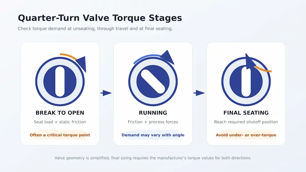
Break-to-open torque, often abbreviated BTO, is the torque required to move a closed valve away from its seat. It is also called break torque, breakout torque or breakaway torque. For many soft-seated ball valves, BTO is a critical point because seat contact, pressure loading and static friction act together while the valve has been stationary.
Break torque can increase after long idle periods, temperature cycling, seat swelling, deposits, corrosion or loss of lubrication. A value measured on a clean new valve at ambient temperature may therefore be lower than the torque required after months in actual service.
Running Torque
Running torque is the torque required while the valve travels between its end positions. It is not necessarily constant. Bearing friction, packing load, fluid forces and valve geometry can make the demand change with angle.
For a ball valve, running torque is often lower than the initial unseating demand, but that should not be assumed without valve data. Butterfly valves can develop significant dynamic torque under flow, and the magnitude and direction can change with disc angle, velocity and differential pressure. Plug valves may retain substantial friction through a larger portion of their stroke.
End-to-Open and Break-to-Close Torque
End-to-open torque is the demand near the fully open position. Break-to-close torque is the torque required to start moving from fully open toward closed. These values matter when a process valve must reliably reverse direction from either end position.
They are sometimes omitted from simplified torque tables. If the valve or process produces an asymmetric torque profile, assuming that opening and closing are identical can undersize one direction.
Seating or End-to-Close Torque
Seating torque is required near the end of the closing stroke to reach the specified closed position and compress or engage the sealing system as designed. Too little torque can leave the valve short of its seat and cause leakage. Excess torque can damage a soft seat, deform a stem or coupling, overload a gearbox, or create repeated torque trips.
Do not increase the actuator setting simply to compensate for a valve that no longer seats normally. Misalignment, deposits, seat damage, thermal distortion or an obstruction must be investigated rather than forced through with more torque.
Where the Valve Torque Data Should Come From
The valve manufacturer should provide the required torque values for the actual valve construction and identify the angle and direction at which each maximum occurs. The data should correspond to the selected:
- Valve type, size and pressure class
- Body, trim, seat, seal and packing materials
- Maximum differential pressure in each flow direction
- Operating and design temperatures
- Medium and expected solids, deposits or viscosity
- Operating frequency and expected idle periods
- Required leakage or shutoff performance
Do not size from a torque value copied from another manufacturer’s valve of the same nominal size. Stem diameter, seat design, bearing system, surface finish, tolerances and pressure loading can produce materially different torque demands.
If certified torque data are unavailable, the supplier should state the basis of the estimate and the uncertainty applied. For critical isolation, emergency shutdown, high-pressure gas or severe chemical service, uncertainty should be resolved through engineering review or testing rather than hidden inside an arbitrarily oversized actuator.
How Process Conditions Change Required Torque
Published valve torque is only useful when its test basis matches the service. The following conditions commonly require correction or additional margin:
| Service condition | Possible effect on torque | What to confirm |
|---|---|---|
| Higher differential pressure | Increases pressure loading on the closure element or seat | Maximum differential pressure during normal, startup, shutdown and upset conditions |
| Low temperature | Can increase seal stiffness, packing friction and lubricant resistance | Minimum operating and ambient temperature, not only normal temperature |
| High temperature | Can change seat interference, clearances, packing load and material strength | Maximum process temperature and thermal cycling |
| Dry gas or infrequent operation | May increase static friction after long stationary periods | Longest expected idle time and cycling schedule |
| Slurry, scale or crystallizing media | Deposits can obstruct movement and increase seat or bearing friction | Solids content, particle size, flushing and cleaning arrangement |
| Sticky or high-viscosity media | Can increase drag and breakaway demand | Viscosity at the lowest service temperature |
| High cycle duty | Raises heat, wear and duty-related actuator limitations | Cycles per hour, travel time and modulating duty |
| Ageing seats or packing | Friction can increase over the service interval | Maintenance interval and expected end-of-run condition |
These effects should be addressed using valve-manufacturer service factors or application-specific corrections whenever available. A general safety factor is not a substitute for understanding the service.
How to Apply a Safety Factor
A safety factor adds margin between the expected valve demand and the minimum actuator output. In its simplest form:
Design torque = verified valve torque × approved safety factor
Apply this formula at each relevant torque point, not only at break torque. The approved factor should follow the valve manufacturer recommendation, actuator manufacturer guidance or project specification, and it should not be counted again if the valve torque data already include a documented service margin.
For example, if the verified break-to-open torque is 400 Nm and the approved factor is 1.25, the design value for that position is 500 Nm. This is only an example for that position, not a universal sizing percentage.
This equation is simple; choosing the factor is not. Emerson publishes an actuator sizing example using 1.2, or 20%, but that is an example for the stated calculation—not a universal industrial rule. The required margin depends on how the original valve torque was established, whether it already includes service factors, the severity of the application, the certainty of the power supply and the project specification.
Avoid Double-Counting Margin
Ask whether the valve torque table is:
- A raw test value
- A calculated nominal value
- A maximum required torque
- Already corrected for differential pressure and temperature
- Already supplied with a manufacturer-recommended safety factor
Applying another blanket factor to a number that already includes margin can produce unnecessary oversizing. Oversizing increases cost and can make a mechanical overload more severe.
When More Margin May Be Needed
Additional margin may be justified when torque data are uncertain, the valve remains idle for long periods, deposits or polymerization are credible, temperatures materially increase friction, or a safety function requires dependable movement under degraded conditions. The amount should be agreed by the valve supplier, actuator supplier and project engineer.
More margin does not cure an unsuitable valve design. If solids can pack into cavities, materials swell in the medium, or the valve is prone to thermal binding, the correct response may be a different valve, seat, flushing arrangement or operating procedure.
Match the Full Torque Curves
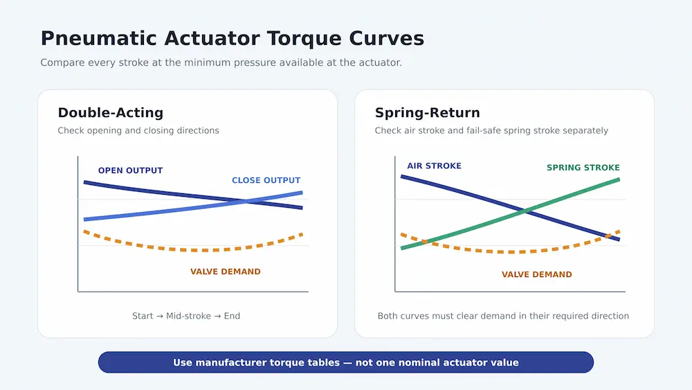
After correcting the valve demand, compare it with actuator output at each relevant position. The actuator must stay above the required curve throughout opening and closing.
Double-Acting Pneumatic Actuators
For a double-acting actuator, check output in both directions at the minimum available air pressure at the actuator, not the compressor nameplate pressure or the plant header pressure. Catalogue tables are pressure-specific. Selecting from a 6 bar column is invalid if the actuator may receive only 4.5 bar after filter-regulator loss, tubing loss, solenoid valve flow limitation and simultaneous air demand. For air supply capacity checks, also review pneumatic actuator air consumption.
Use the actuator manufacturer’s start, mid-stroke and end torque values or full curve. A single nominal output number can hide a deficit where the mechanism produces less torque.
Spring-Return Pneumatic Actuators
A spring-return actuator has two different output profiles:
- The air stroke, where pneumatic force works against the spring
- The spring stroke, where stored spring force drives the valve after air is removed
Check both strokes independently. The spring-end torque must be sufficient to complete the required fail action, while the air stroke must overcome the valve plus the spring load at minimum air pressure. A unit that opens correctly during commissioning can still fail to close safely after air loss if only the air stroke was checked.
The fail direction must be defined from the process safety requirement, not from actuator convenience. Review fail-close vs fail-open valve selection before assigning the actuator orientation, then match the actuator output curve against the valve torque demand curve on both strokes.
Rack-and-Pinion vs Scotch-Yoke Output
Rack-and-pinion and scotch-yoke actuators do not necessarily produce the same torque profile. A scotch-yoke mechanism can provide higher output near the ends of travel and lower output near mid-stroke, which can suit certain quarter-turn valve demand profiles. The comparison still has to use the actual manufacturer curve; mechanism type alone does not guarantee correct sizing.
Electric Actuators
For an electric actuator, confirm rated torque, starting torque, permissible seating torque, torque-switch settings and maximum output because these values may differ on the selected model. Do not increase the torque switch setting to force a damaged, obstructed or misaligned valve. Also verify:
- Supply voltage, phase and frequency
- Permitted voltage variation
- Open-close, positioning or modulating duty
- Starts per hour and running time
- Ambient temperature, enclosure and hazardous-area requirements
- Motor and gear thermal limits
Some electric actuators can provide increased torque briefly during unseating, but that feature must be confirmed from the selected model’s documentation and settings. It should not be assumed from nominal rated torque. Modulating duty and open-close duty should not be treated as the same sizing case. Buyers comparing automated valve options can also review the electric ball valve selection guide.
Check Maximum Allowable Stem Torque
Minimum output is only half the sizing envelope. The actuator’s highest deliverable or set torque must remain below the weakest allowable limit in the mechanical chain. This may include:
- Maximum allowable valve stem torque
- Gearbox input or output torque limit
- Key, square drive or spline capacity
- Coupling and adaptor capacity
- Mounting bracket strength
- Actuator-valve flange reference torque
The maximum allowable stem torque is often abbreviated MAST. It is not the torque required to operate the valve. It is a structural limit. A valid selection therefore satisfies both conditions:
Minimum actuator output > corrected valve demand at every required position
Maximum possible actuator output or torque setting < applicable valve and drive-train limits
If these conditions cannot both be met, simply choosing a larger actuator is unsafe. Review the stem design, gearbox, coupling, mounting kit, actuator control settings or valve construction before approving the package. MAST is a structural limit, not the required operating torque.
Worked Quarter-Turn Sizing Example
Assume a valve manufacturer supplies the following maximum required torque values for a quarter-turn ball valve at the project differential pressure and temperature:
| Valve position | Published requirement | Approved factor | Design requirement |
|---|---|---|---|
| Break to open | 400 Nm | 1.25 | 500 Nm |
| Mid-stroke running | 240 Nm | 1.25 | 300 Nm |
| End to close | 320 Nm | 1.25 | 400 Nm |
A candidate double-acting pneumatic actuator produces, at the minimum available air pressure:
- 560 Nm at the start of opening
- 420 Nm at mid-stroke
- 470 Nm at the end of closing
The actuator exceeds the design requirement at all three checked points. It passes the minimum-output comparison.
Now assume its highest possible output at maximum supply pressure is 720 Nm, while the confirmed valve MAST and all drive-train limits are above 900 Nm. It also passes the preliminary overload check. The selection is not complete until the mounting interface, stroke time, air consumption, duty, fail action, accessories and environmental conditions are confirmed, but the torque comparison is acceptable.
If the actuator produced only 280 Nm at mid-stroke, it would fail even though its start torque exceeded the 500 Nm break requirement. If its maximum possible output exceeded the stem or coupling limit, it would also fail despite having ample operating torque.
Mounting and Alignment Can Change the Field Result
A correct calculation can still produce poor operation if the actuator is mounted badly. Side loading, an off-centre bracket, an incorrect drive adaptor or insufficient coupling engagement can increase friction and concentrate stress.
ISO 5211:2026 defines requirements for part-turn actuator attachment interfaces, including flange and drive-component dimensions and reference torque values. It does not remove the need to engineer the intermediate bracket and coupling for the actual load. Where direct mounting is impractical, the complete mounting kit must transmit torque without excessive deflection or backlash. For mounting details, see our ISO 5211 actuated valve mounting guide.
Check actuator and valve alignment through the full stroke before increasing torque settings. See the guide to misaligned valve actuators for common mechanical consequences.
Common Actuator Sizing Mistakes
Using Only Nominal Valve Size
Two DN100 or 4-inch valves can require different torque because their pressure class, seat material, stem, bearing system and differential pressure differ. Size is not a torque specification.
Checking Only Break Torque
Break-to-open may be the largest demand, but it is not automatically the only critical point. Running, reverse-direction and seating requirements still need comparison.
Using Normal Air Pressure Instead of Minimum Available Air Pressure
Pneumatic output falls with supply pressure. Sizing at a convenient catalogue pressure can leave no torque margin during peak plant air demand or accessory pressure loss.
Ignoring the Spring Stroke
A spring-return actuator must operate the valve with stored spring energy during the fail stroke. Air-stroke performance alone cannot prove the fail-open or fail-close action.
Applying a Universal Safety Factor
A fixed percentage does not capture unknown deposits, low-temperature seal friction or uncertain valve data. It may also duplicate margin already included by the valve manufacturer.
Ignoring MAST
MAST is a structural limit, not a target operating torque. Maximum supply pressure and actuator torque settings must be included in the overload check.
Confusing Torque with Thrust
This guide focuses primarily on part-turn valves. Multi-turn gate and globe valves may require thrust calculations in addition to input torque, based on stem geometry, differential pressure, packing and seating load.
Oversizing Actuator Without Checking Stem / Gearbox Limits
A larger actuator can damage the valve stem, gearbox, coupling or mounting hardware if its maximum output exceeds the mechanical limit. More torque is not automatically a safer selection.
Using Torque Data from Another Manufacturer’s Valve
Torque from a similar-looking valve can be wrong because seat design, coating, packing, stem diameter and pressure class vary by manufacturer. Use verified torque data for the exact valve construction being quoted.
Actuator Torque Sizing Workflow
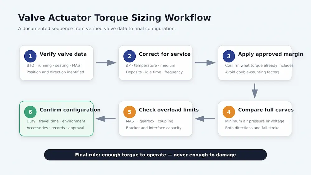
- Define valve function, normal position and required fail position.
- Obtain manufacturer torque data for the exact valve construction.
- Confirm maximum differential pressure in both flow directions.
- Correct the valve torque for actual medium, temperature, deposits, frequency and idle time.
- Confirm whether the supplied values already include service margin.
- Apply the project-approved safety factor where required.
- Identify minimum pneumatic pressure or worst electrical supply condition at the actuator.
- Compare actuator output and valve demand at each critical point in both directions.
- For spring return, check air and spring strokes separately.
- Check MAST, gearbox, drive, coupling, bracket and interface limits at maximum possible output.
- Confirm duty cycle, operating time, starts per hour, environment and accessories.
- Document the assumptions and approved configuration in the datasheet or quotation.
Information Buyers Should Provide Before Actuator Sizing
Before requesting a pneumatic or electric actuator selection, provide enough data for the valve supplier to check both required torque and allowable mechanical limits:
- Valve type: ball, butterfly, plug, gate, globe or control valve
- Valve size / DN / NPS and pressure class / PN / Class
- Valve model, drawing, stem size, drive connection and ISO 5211 mounting interface if available
- Opening direction and required fail position: fail-open, fail-close or fail-last
- Medium, operating pressure, design pressure and maximum differential pressure
- Operating temperature, design temperature, clean media, slurry, viscous fluid or crystallizing media
- Required leakage class or shutoff condition
- Break-to-open torque, running torque, break-to-close torque and seating torque
- Maximum allowable stem torque / MAST and any gearbox, coupling or mounting limits
- Required safety factor or project sizing margin
- Available air pressure range and minimum air pressure at the actuator for pneumatic actuators
- Voltage, phase, frequency, control mode, duty cycle and starts per hour for electric actuators
- Required accessories: solenoid valve, limit switch, positioner, handwheel, gearbox or local controls
- Enclosure / IP rating / hazardous-area requirement and documentation requirement
For actuator sizing, incomplete torque and power supply data can result in an actuator that moves during commissioning but fails under real operating conditions. For automated ball-valve applications, Vcore Valve can review the valve construction and actuator configuration together. Related resources include industrial ball valves, soft seat vs metal seat ball valve selection and valve actuator selection.
Engineering Decision Summary
Valve actuator torque sizing is a curve-matching and limit-checking exercise, not a one-number comparison. The actuator must exceed corrected valve demand at breakaway, through travel and at final seating in both required directions. Pneumatic selection must use the minimum available air pressure, and spring-return selection must verify the air and spring strokes independently. Electric selection must include supply variation, duty and torque-control behavior.
The selected actuator must also stay within the maximum allowable torque of the stem, gearbox, coupling and mounting interface. A larger actuator is not automatically safer. Reliable selection comes from verified valve torque data, explicit service assumptions and a documented comparison of the complete valve and actuator torque profiles.
Torque sizing is only one part of actuator selection. Power source, valve movement, fail action, control mode, duty, environment and mounting must also be reviewed. See our complete valve actuator selection guide for the full selection process.
To request a configuration review, send Vcore Valve the valve type, size, pressure class, medium, differential pressure, temperature, operating frequency, required fail position, available power supply and project documentation requirements through the valve project enquiry page.
Frequently Asked Questions
What is valve actuator torque sizing?
Valve actuator torque sizing is the process of comparing the actuator output curve with the valve torque demand curve through the required opening and closing strokes. It also checks that maximum actuator output stays below MAST and other drive-train limits.
What is break torque in a valve?
Break torque is the torque required to move a valve away from a stationary end position. Break-to-open torque is often critical because seat load and static friction act together when a closed valve first begins to move.
Is running torque always lower than break torque?
No. It is often lower for some ball-valve designs, but valve geometry, differential pressure, fluid forces, deposits and friction can create another critical point during travel. Use the valve manufacturer’s full torque data rather than assuming a generic profile.
What safety factor should be used for actuator sizing?
There is no universal factor for every valve and service. The factor should follow the valve manufacturer’s recommendation, actuator manufacturer guidance or project specification, considering whether the published torque already includes service corrections.
Why must a pneumatic actuator be sized at minimum air pressure?
Actuator output decreases with available air pressure. Pressure loss through filter regulators, tubing, solenoid valves and simultaneous plant demand can make the pressure at the actuator lower than the compressor or header pressure.
How do you size a spring-return actuator?
Check the air stroke and spring stroke separately against the valve torque demand curve. The fail direction must be defined by the process safety requirement, and the spring stroke must complete the required fail-open or fail-close action after air is lost.
Can an actuator be too large for a valve?
Yes. Excess output can overload the valve stem, gearbox, drive adaptor, coupling or mounting bracket. Maximum actuator output and torque settings must remain below the applicable mechanical limits.
What is the difference between valve torque and MAST?
Valve torque is the amount required to operate the valve. Maximum allowable stem torque, or MAST, is a structural limit that should not be exceeded. A correct selection provides enough operating torque while remaining below MAST and other drive-train limits.