Quick Answer: Choose an electric valve actuator control signals according to the required valve function and the PLC or DCS interface. Use discrete OPEN/CLOSE commands for basic isolation, a modulating input such as 4–20 mA or 0–10 V for proportional positioning, and fieldbus communication when digital status, diagnostics or network control is required. Specify command input, position feedback, end-position contacts, fault outputs and power supply separately. A 4–20 mA command does not automatically include 4–20 mA feedback, and an actuator should not be connected until signal type, voltage, active/passive loop arrangement, fail behavior and terminal diagram have been confirmed.
Electric valve actuators are often ordered with descriptions such as “220 V electric actuator,” “4–20 mA control” or “with feedback.” None of these descriptions is complete enough for reliable PLC or DCS integration.
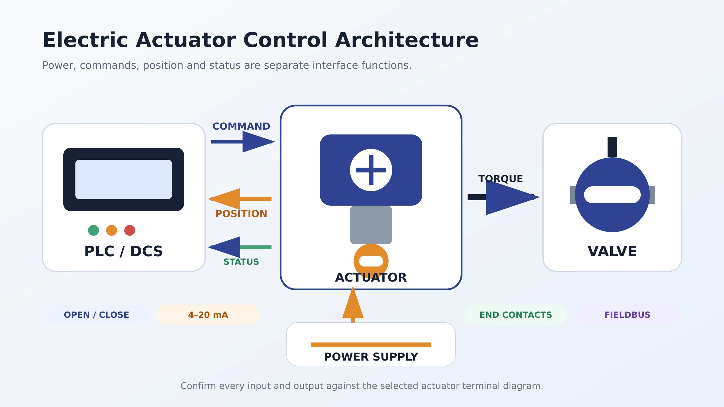
The power supply tells the actuator where its operating energy comes from. The control input tells it what movement is required. Feedback tells the control system what position or condition has been reached. These are separate parts of the interface and may use different voltages, terminals and signal types.
A technically correct actuator order should define all of them before manufacturing. Otherwise, the valve may arrive with the correct torque and mounting flange but still be unusable with the site control panel.
Start by Separating Power, Command and Feedback
The most important first step is to divide the actuator interface into distinct functions.
| Interface function | What it does | Common examples |
|---|---|---|
| Power supply | Provides energy for the motor, electronics and optional heater | 24 VDC, 110–120 VAC, 220–240 VAC, three-phase AC |
| Control command | Tells the actuator to open, close, stop or move to a target position | Dry contact, switched voltage, 4–20 mA, 0–10 V, fieldbus command |
| Position feedback | Reports actual valve or actuator position | Open/closed contacts, 4–20 mA transmitter, digital position value |
| Status and alarm output | Reports actuator condition or fault | Local/remote, torque trip, motor thermal fault, power loss, collective fault |
| Communication | Exchanges commands, status, parameters and diagnostics | Modbus RTU, Profibus, Foundation Fieldbus or manufacturer-supported protocol |
Do not assume that the control signal voltage is the actuator power voltage. A 230 VAC actuator may accept a 24 VDC command, dry-contact command, 4–20 mA analog input or fieldbus instruction depending on its control module.
On/Off Electric Actuator Control
On/off control is used when the valve normally operates fully open or fully closed. Typical applications include pipeline isolation, tank inlet and outlet control, batch transfer, bypass switching and emergency process sequencing.
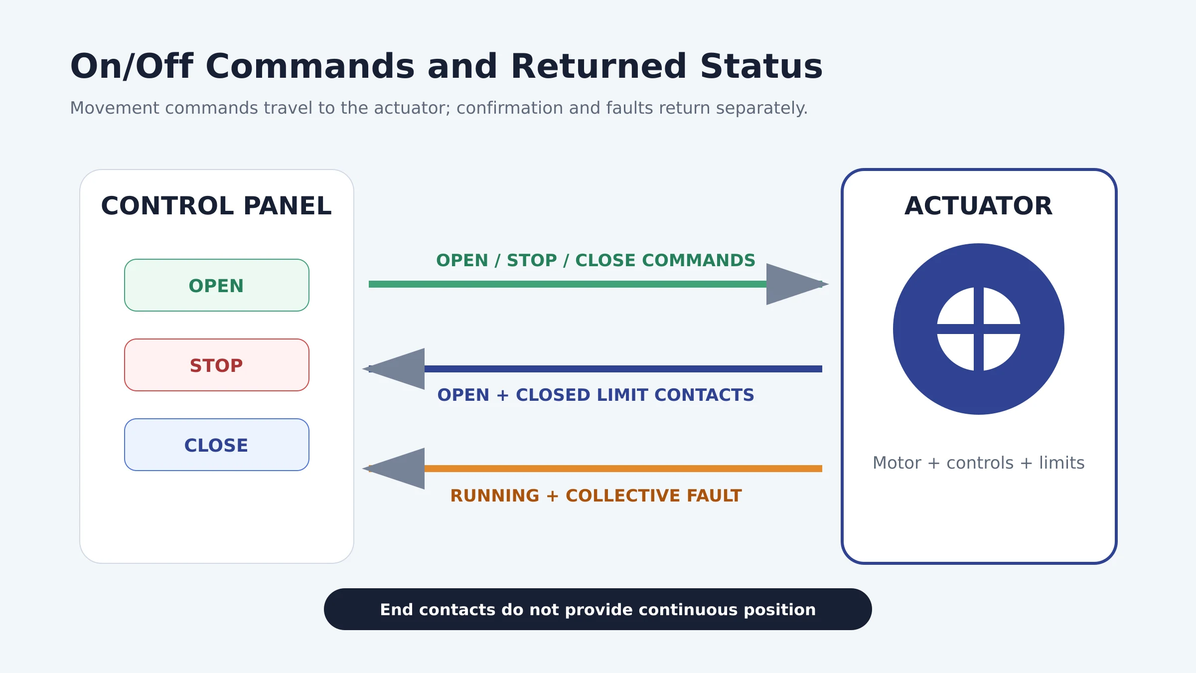
OPEN, STOP and CLOSE Commands
Many industrial electric actuators use separate OPEN, STOP and CLOSE control commands. Depending on the control logic, the command may be maintained until the end position is reached or applied as a pulse that latches an internal control circuit.
The actuator manufacturer may describe these modes as maintained-contact, push-to-run, inching or self-retaining control. The PLC logic and actuator configuration must use the same operating philosophy.
AUMA’s basic actuator-control documentation, for example, describes OPEN, STOP and CLOSE commands with end-position and fault signals returned to the DCS. This illustrates why a simple “on/off actuator” description is still incomplete: the buyer must define the command voltage, contact behavior and returned signals.
Dry Contact vs Switched Voltage
A dry contact is a potential-free contact that opens or closes a circuit without intentionally supplying an external voltage. Some actuator inputs provide their own sensing or wetting voltage and only require the remote contact to close. Other inputs expect the PLC or control panel to apply a specified voltage.
These arrangements are not interchangeable. Before wiring, confirm:
- Input voltage and current
- Whether the actuator or control panel supplies the sensing voltage
- Common terminal arrangement
- Whether inputs are isolated
- Maintained or pulse command logic
- Priority of STOP, ESD and local controls
Open and Closed Limit Feedback
On/off actuators commonly return separate open-limit and closed-limit indications through potential-free contacts or electronic outputs. These signals confirm that the actuator has reached its configured end positions.
End-position feedback is not continuous position feedback. If neither contact is active, the valve may be travelling, stopped at an intermediate position, locally operated, unpowered or faulted. A control system that needs to distinguish these conditions requires additional status signals or a position transmitter.
Modulating Electric Actuator Control
A modulating actuator moves the valve to intermediate positions according to a continuously changing command. It is used for flow, pressure, temperature, level or process-ratio control when the selected valve is suitable for throttling.
The actuator must be designed for modulating duty. Adding a 4–20 mA module to a basic open-close actuator does not automatically make the motor, gearing and controls suitable for frequent positioning. Duty classification, starts per hour, positioning accuracy, deadband, motor heating and mechanical wear must be reviewed.
Before deciding whether modulation is necessary, compare on-off valves vs modulating valves.
4–20 mA Control Input
In a common direct-acting configuration, 4 mA commands the minimum position and 20 mA commands the maximum position. For a quarter-turn valve this may correspond to 0° and 90°, but the relationship can be configured differently. Some applications use reverse action, limited travel or split ranges.
The 4 mA lower value provides a live zero. A signal near 0 mA can therefore be recognized as a broken wire, lost loop power or another fault when the system is designed to detect it. Exact alarm thresholds and fail responses must be configured in the controller and actuator rather than assumed.
0–10 V and Other Voltage Inputs
Voltage signals such as 0–10 V, 2–10 V or 1–5 V are available on selected actuators. They are common in HVAC and some industrial control systems. Correct operation depends on compatible input impedance, reference potential, wiring length, grounding and electrical-noise conditions.
Do not substitute 0–10 V for 4–20 mA merely because both represent 0–100% position. The PLC output card and actuator input module must support the same signal.
Floating or Three-Point Control
Floating control uses separate commands to drive the actuator in the opening or closing direction without transmitting an absolute analog target. The controller estimates or adjusts position based on travel time and process response.
This approach may be suitable for selected systems, but it should not be confused with analog position control. If accurate actual position is required, add continuous position feedback or use an actuator with internal positioning control.
Command Signal and Position Feedback Are Different
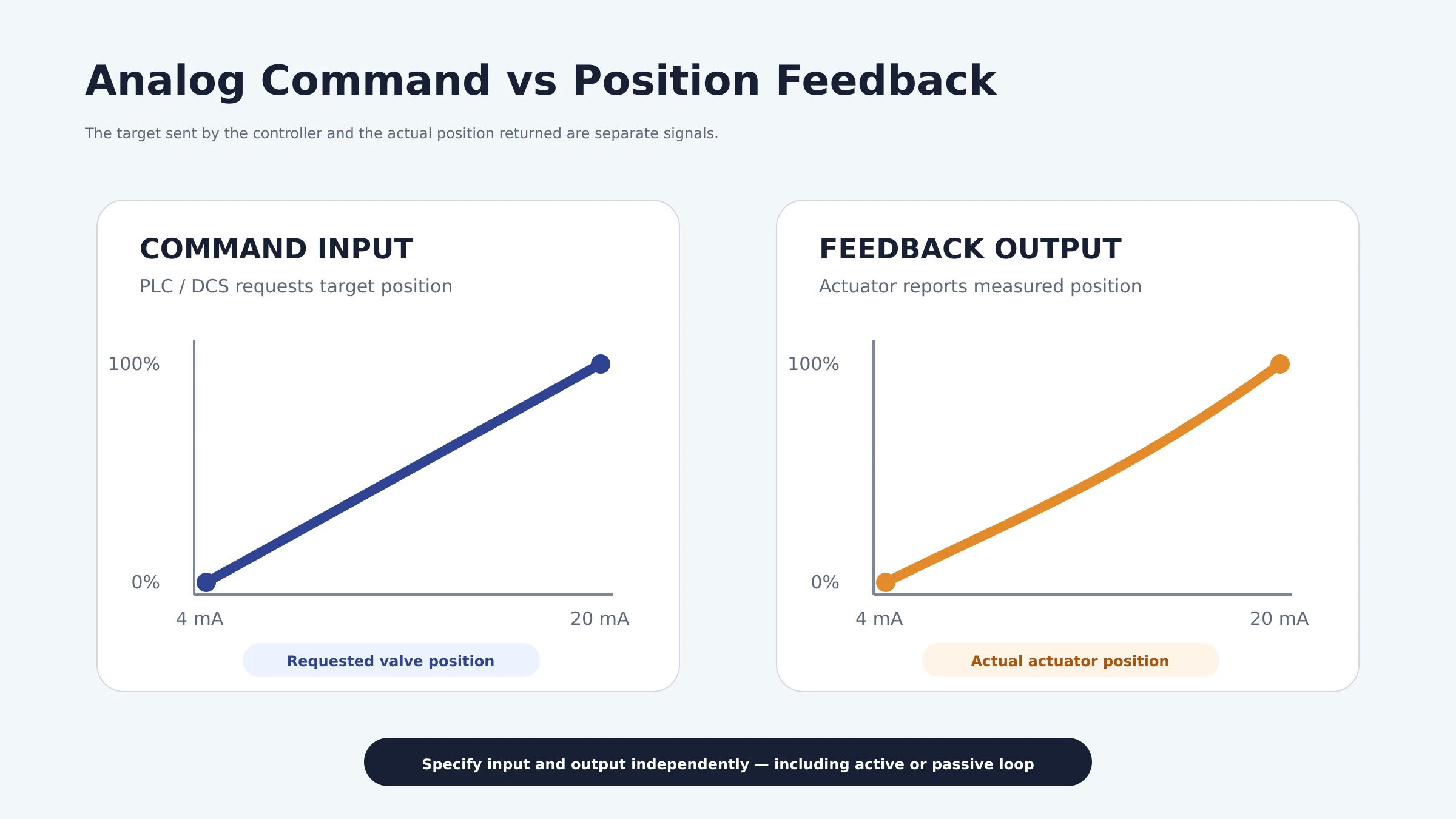
A frequent specification error is writing only “4–20 mA” without saying whether it is an input, output or both.
- 4–20 mA command input: the PLC or DCS requests a target position.
- 4–20 mA position feedback output: the actuator reports its measured position.
- Discrete end-position feedback: contacts indicate fully open or fully closed.
- Fault/status output: a relay or digital status reports an abnormal condition.
An actuator can include one of these functions without the others. A complete purchase description might therefore require “4–20 mA modulating input, isolated 4–20 mA position retransmission, two end-position contacts and one collective-fault relay.” Final terminology should match the selected manufacturer’s datasheet.
Active and Passive Current Loops
A 4–20 mA interface may be active or passive. An active device supplies loop power; a passive device requires power from another device. Connecting two active outputs together or leaving a passive loop without a supply can prevent operation or damage equipment.
For each analog input and output, confirm:
- Active or passive loop arrangement
- Required loop supply voltage
- Maximum permitted load or input resistance
- Galvanic isolation
- Signal common and grounding arrangement
- Behavior below 4 mA or above 20 mA
These details must come from the actuator and control-system terminal documentation. Wire color or general industry habit is not a sufficient basis.
Position Feedback Options
| Feedback method | Information provided | Typical use | Important limitation |
|---|---|---|---|
| Open/closed limit contacts | Two end states | Basic on/off confirmation | Does not show intermediate position |
| Potentiometer | Resistance related to travel | Local or panel-based position measurement | Requires compatible measuring circuit and calibration |
| 4–20 mA transmitter | Continuous percentage of travel | Remote analog position indication | Active/passive and scaling must be confirmed |
| Digital fieldbus value | Position plus status and possible diagnostics | Networked control systems | Protocol and device integration must match |
The feedback device generally measures actuator or output-drive position. It does not prove that the internal valve closure element is undamaged or sealing correctly. A disconnected coupling, damaged stem or slipping drive can produce misleading position indication unless the assembly has suitable mechanical integrity and diagnostics.
Fault and Status Signals Buyers Should Define
Open and closed indications are rarely enough for a critical automated valve. Depending on the actuator, useful status signals may include:
- Torque trip during opening or closing
- Motor thermal overload
- Loss of phase or incorrect phase condition
- Local, stop or remote selector status
- Actuator running
- Intermediate or commanded-position reached
- Power-supply fault
- Communication fault
- Collective or general fault
Specify whether outputs are normally open or normally closed and what state represents healthy operation. A normally energized healthy relay can help the control system recognize loss of actuator power or a broken circuit, but the final design must follow the project’s control and safety philosophy.
Fieldbus and Digital Communication
Digital communication can carry commands, position, status, diagnostics and parameter data over one network. Available protocols depend on the actuator control unit and may include Modbus RTU, Profibus, Foundation Fieldbus or other manufacturer-supported systems.
Do not specify only “Modbus” or “fieldbus.” Confirm:
- Exact protocol and physical layer
- RS-485, Ethernet or other network medium
- Baud rate, addressing and termination
- Required device-description or integration files
- Single or redundant communication
- Which commands and diagnostics are available
- Behavior after communication loss
- Whether hardwired ESD or end-position signals remain required
A digital network may reduce field wiring and improve diagnostics, but it also creates commissioning and compatibility requirements. Critical shutdown functions should follow the approved safety architecture rather than relying on convenience.
What Happens When the Signal or Power Is Lost?
Signal-loss behavior and power-loss behavior are not the same.
For loss of an analog command, a configurable actuator may hold its last position, move to a predefined position, continue using the last valid value or report a fault. For loss of main electrical power, a standard motorized actuator generally cannot move unless it has stored-energy equipment such as a spring mechanism, battery, supercapacitor or supported backup supply.
Never write “fail close” for an ordinary electric actuator without confirming how the closing energy is provided. Define separately:
- Action on control-signal loss
- Action on communication loss
- Action on main-power loss
- Required emergency shutdown input
- Whether emergency commands override local or remote control
- Required travel time to the safe position
Control Signal Selection Table
| Required function | Typical command | Recommended feedback | Main checks |
|---|---|---|---|
| Basic isolation | Discrete OPEN/CLOSE | Open and closed contacts | Voltage, contact logic, local/remote status |
| Isolation with fault monitoring | Discrete OPEN/STOP/CLOSE | End contacts plus collective fault | Healthy relay state, torque trip, thermal fault |
| Proportional positioning | 4–20 mA or 0–10 V | Continuous position plus fault | Scaling, action direction, deadband, duty |
| Networked actuator | Fieldbus command | Digital position, status and diagnostics | Protocol, redundancy, integration files, loss behavior |
| Emergency movement | Dedicated ESD or safety-system command | Safe-position and fault confirmation | Command priority, independent energy and travel time |
Commissioning Checks
Before energizing the actuator, compare the approved wiring diagram with the actuator terminal plan and control-panel drawings. Commissioning should include:
- Verify power voltage, phase, frequency, polarity and protective devices.
- Confirm protective earth and specified shielding or grounding arrangement.
- Check command-input voltage and common terminals.
- Confirm active/passive arrangement for every analog loop.
- Test local operation and mechanical travel before remote commands.
- Verify opening direction and direct or reverse analog action.
- Calibrate 0%, intermediate and 100% positions where applicable.
- Test open, closed, running and fault indications at the PLC or DCS.
- Simulate command loss, communication loss and permitted fault conditions.
- Confirm torque and limit settings without exceeding the approved valve limits.
- Record final parameters, terminal numbers and test results.
Torque selection remains a separate mechanical requirement. Use the valve actuator torque sizing guide to confirm break, running and seating torque before final actuator configuration.
RFQ Checklist for Electric Actuator Controls
| Item | Information to provide |
|---|---|
| Valve duty | On-off, positioning or modulating; normal and fail position |
| Valve and torque | Valve type, size, BTO/running/seating torque, MAST and travel |
| Power supply | Voltage, phase, frequency, allowable variation and backup availability |
| Command input | Dry contact, switched voltage, 4–20 mA, 0–10 V, floating or fieldbus |
| Position feedback | Open/closed contacts, 4–20 mA output, potentiometer or digital value |
| Status outputs | Running, local/remote, torque trip, thermal trip, collective fault and power status |
| Analog-loop details | Active/passive, loop voltage, load, isolation and direct/reverse action |
| Communication | Exact protocol, medium, addressing, redundancy and loss behavior |
| Duty and speed | Cycles or starts per hour, modulating duty and required travel time |
| Environment | Ambient temperature, indoor/outdoor location, enclosure, corrosion and hazardous-area requirements |
Vcore Valve can review the valve, actuator and control interface as one assembly. Related resources include the electric ball valve selection guide, electric ball valves in chemical plants and electric valve actuator brand and specification guide.
Engineering Decision Summary
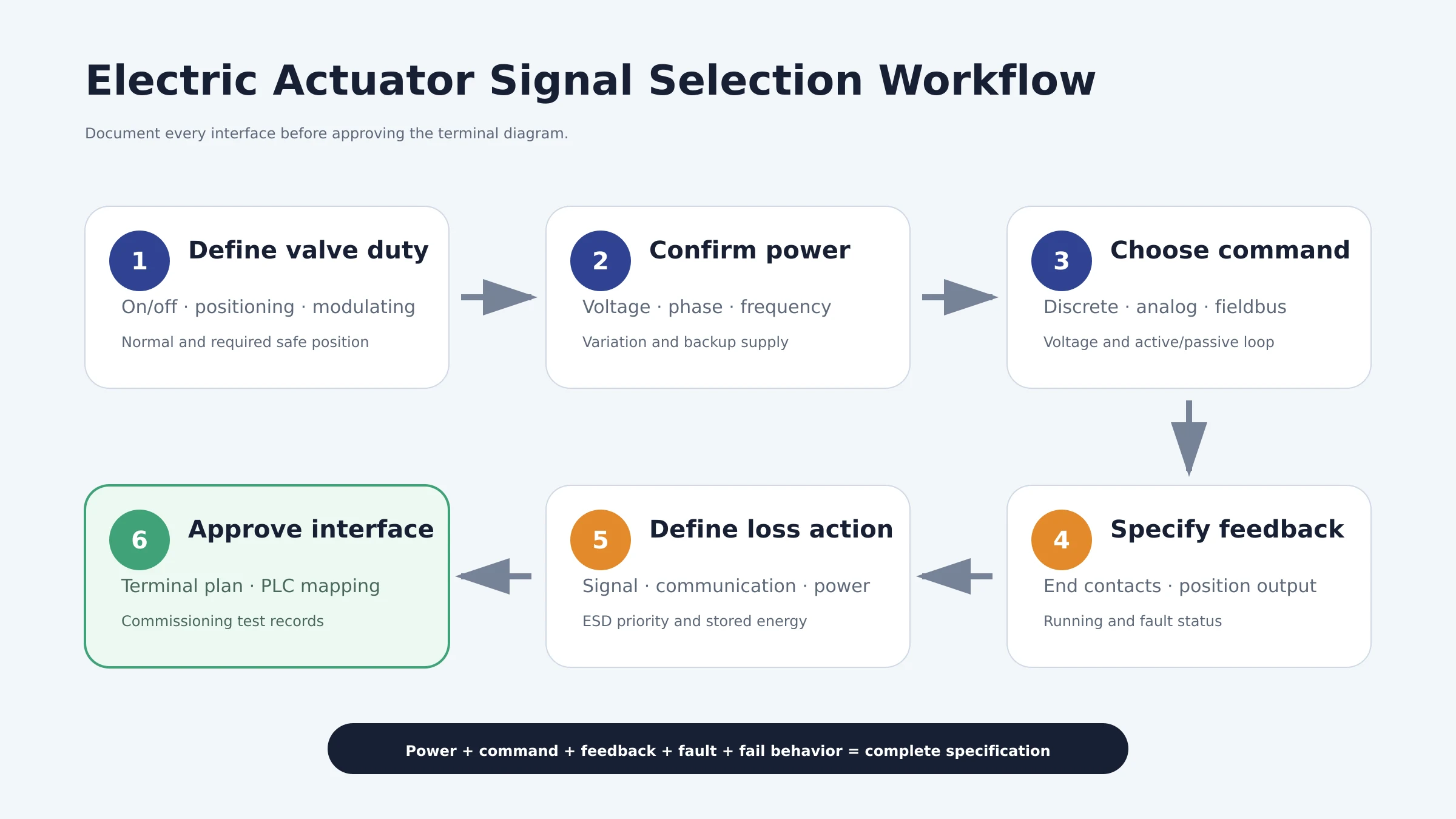
Electric valve actuator control signals should be selected from the required process function and control-system architecture. Discrete commands are appropriate for basic opening and closing. Analog signals support proportional positioning when the valve and actuator are designed for modulating duty. Fieldbus communication can add diagnostics and reduce wiring, but only when the protocol and system integration are fully defined.
Always specify power, command input, position feedback, end contacts, alarms and fail behavior separately. Confirm active/passive analog-loop arrangements and control voltages before wiring. The most reliable purchase specification is not “electric actuator with 4–20 mA”; it is a documented interface schedule that tells the supplier exactly what the control system sends, what the actuator returns and what must happen when a signal or power source is lost.
Control signals are only one part of the complete actuator specification. Actuator type, torque or thrust, fail position, operating duty, enclosure protection and mounting must also be confirmed. Review our valve actuator selection guide before finalizing the complete package.
For an actuator configuration review, send Vcore Valve the valve type, torque data, supply voltage, control command, feedback requirement, duty, travel time, fail action, enclosure and communication requirements through the valve project enquiry page.
Frequently Asked Questions
What is the difference between on/off and modulating actuator control?
On/off control normally moves a valve fully open or fully closed. Modulating control moves the valve to intermediate positions according to an analog or digital target and requires an actuator designed for frequent positioning duty.
Is a 4–20 mA command the same as 4–20 mA position feedback?
No. The command input tells the actuator where to move, while the feedback output reports the position reached. They are separate circuits and must be specified independently.
Can a 220 V actuator be controlled by a 24 VDC signal?
Yes, if the selected actuator control module is designed for a 24 VDC input. Motor power voltage and control input voltage can differ, but both must match the approved terminal diagram.
What does dry-contact control mean?
A dry contact is a potential-free switching contact. The complete circuit still needs a compatible sensing or control voltage supplied by the actuator or external control system as defined by the manufacturer.
What happens to an electric actuator when power fails?
A standard motorized actuator normally cannot move without power. Movement to a safe position requires a supported stored-energy or backup arrangement such as a spring, battery, supercapacitor or external backup supply.
Do open and closed limit switches provide continuous valve position?
No. They indicate end positions only. Continuous position indication requires a transmitter, potentiometer or digital position value supported by the actuator.