This valve actuator selection guide explains how to match pneumatic, electric or hydraulic actuation to the valve movement, operating torque or thrust, available utility supply, fail position, control mode, duty, installation environment and mounting interface. The actuator should be selected as part of a complete valve package rather than as an independent accessory. Final selection must be based on confirmed valve operating data and project requirements.
An automated valve is not simply a manual valve with a motor or cylinder added on top. The valve, actuator, mounting kit, controls and feedback devices must work as one engineered assembly under the actual process and site conditions.
A suitable actuator must move the valve through its complete travel, provide adequate output at the most demanding point of the stroke, reach the required position after a defined failure and communicate correctly with the plant control system. It must also fit the valve mechanically without exceeding the allowable load of the stem, shaft, coupling or gearbox.
This valve actuator selection guide provides a practical method for comparing pneumatic, electric and hydraulic systems for isolation valves, control valves and emergency shutdown applications.
The actuator power source should not be the first decision. Begin by defining what the complete valve package must do.
| Selection Step | Information to Confirm | Why It Matters |
|---|---|---|
| Valve function | Isolation, throttling, pressure control, emergency shutdown or diversion | Defines control accuracy, speed and fail-position requirements |
| Valve movement | Part-turn, multi-turn or linear | Determines the actuator output motion and mounting arrangement |
| Required output | Torque, thrust, stroke, number of turns and full travel time | Prevents under-sizing and mechanical overloading |
| Available utility | Instrument air, electrical supply, hydraulic pressure or pipeline gas | Narrows the practical actuator options |
| Control requirement | On-off, inching, modulating, local, remote or emergency action | Defines controls, feedback and duty requirements |
| Failure response | Fail-close, fail-open, fail-in-place or controlled shutdown | Determines stored-energy and control architecture |
| Site conditions | Ambient temperature, corrosion, dust, water ingress, vibration and hazardous-area classification | Defines enclosure, materials, certification and protection |
Only after these conditions are known should pneumatic, electric and hydraulic actuator options be compared.
2. Match the Actuator to the Valve Movement
The actuator output movement must correspond to the operating movement of the valve. A correct power source with the wrong motion or interface will not produce a reliable package.
Part-Turn Actuation
A part-turn actuator transmits rotary torque through less than one complete revolution. Most industrial quarter-turn valves normally use approximately 90 degrees of travel.
Typical applications include:
- Ball valves
- Butterfly valves
- Plug valves
- Quarter-turn dampers
Part-turn actuators may use rack-and-pinion, scotch-yoke, vane, worm-gear or other drive arrangements. The selected torque curve must match the valve torque profile rather than only the nominal actuator output.
Multi-Turn Actuation
A multi-turn actuator provides rotary output over one or more complete revolutions. Depending on the valve and drive arrangement, the assembly may also need to accommodate or transmit axial thrust.
Typical applications include:
- Gate valves
- Globe valves with threaded stem mechanisms
- Large sluice gates
- Multi-turn gear-operated valves
The number of stem turns, stem direction, stem diameter, thread details, required seating load and permissible stem thrust must be confirmed.
Linear Actuation
A linear actuator provides thrust over a defined stroke. It is commonly used where the valve closure element moves directly along a straight axis.
Typical applications include:
- Globe control valves
- Angle control valves
- Diaphragm control valves
- Knife gate valves with cylinder operation
Linear actuator selection requires the required thrust, stroke length, direction of action, closing load and available installation height.
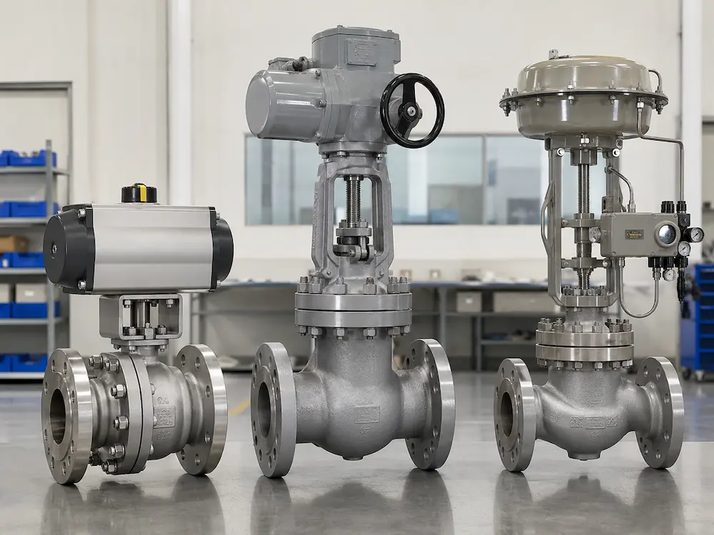
3. Pneumatic vs Electric vs Hydraulic Valve Actuators
No actuator technology is universally superior. The correct choice depends on the valve duty, available utilities, process risk and site infrastructure.
| Selection Factor | Pneumatic Actuator | Electric Actuator | Hydraulic Actuator |
|---|---|---|---|
| Primary utility | Clean compressed air or process gas where specifically engineered | Specified AC or DC electrical power | Pressurized hydraulic fluid from an HPU or dedicated system |
| Common strengths | Fast response, simple spring-return arrangements and broad quarter-turn availability | Useful where instrument air is unavailable; supports remote electrical control and diagnostics | High output force or torque for large and critical valve duties |
| Typical limitations | Requires adequate air quality, pressure, flow capacity and pneumatic accessories | Duty, starting current, enclosure, operating speed and power-loss behavior require careful review | Requires hydraulic equipment, fluid management, leak control and specialized maintenance |
| Fail movement | Often achieved with a spring-return actuator or stored pneumatic energy | Requires a defined stored-energy or backup-power arrangement when movement after power loss is required | Can use spring, accumulator or engineered hydraulic logic |
| Common applications | Process plants, chemical systems, control valves and frequent on-off service | Water systems, utilities, power plants, remote stations and distributed installations | Large pipelines, high-torque isolation valves and critical shutdown systems |
When a Pneumatic Actuator Is Usually Considered
Pneumatic actuation is often practical when a stable instrument-air system already exists and the application requires rapid stroking, frequent cycling or a spring-return fail action.
The minimum available air pressure at the actuator must be used for sizing. Pressure losses through tubing, filters, regulators, solenoid valves and speed controls also need consideration. A pneumatic actuator should not be selected from the compressor discharge pressure alone.
A pneumatic actuator is not automatically suitable for every hazardous location. Solenoid valves, positioners, limit switches, transmitters and junction boxes are electrical devices and must comply with the project area classification.
When an Electric Actuator Is Usually Considered
Electric actuation is useful where electrical power is available but a centralized instrument-air system is not. It is frequently selected for remote pipelines, water treatment facilities, power and utility systems, tank farms and low-frequency isolation duties.
Selection must confirm:
- Power supply voltage, phase and frequency
- On-off, inching or modulating duty
- Required operating time
- Motor starting current and available electrical capacity
- Control inputs and position feedback
- Ingress protection and hazardous-area requirements
- Behavior after loss and restoration of power
A standard electric actuator does not automatically drive the valve to a safe position after power is lost. Where post-failure movement is required, the package needs a verified spring mechanism, battery, supercapacitor, UPS, electro-hydraulic system or another approved stored-energy arrangement.
When a Hydraulic Actuator Is Usually Considered
Hydraulic actuation can provide high force or torque from a comparatively compact actuator. It is therefore considered for large valves, high differential pressure, critical pipeline isolation and emergency shutdown duties.
The complete system may require a hydraulic power unit, reservoir, pump, accumulator, control manifold, filters, tubing and fluid-condition monitoring. These components add engineering and maintenance requirements that should be evaluated against the benefit of the higher output capability.
4. Size the Actuator from Actual Valve Torque or Thrust
Actuator sizing based only on nominal valve size and pressure class is unreliable. The required output changes with the valve design, seat material, differential pressure, temperature, media, operating frequency and time in one position.
For part-turn valves, the manufacturer should identify the relevant torque values across the stroke. Depending on valve type, these may include:
- Breakaway torque from the fully closed position
- Running torque through the middle of travel
- End-to-open torque
- End-to-close or reseating torque
- Maximum torque under differential pressure
For linear valves, specify thrust rather than relying on rotary torque. Required information normally includes:
- Maximum opening and closing thrust
- Required valve stroke
- Seat load or shutoff force
- Packing friction
- Process force acting on the plug, disc or gate
- Required stroking time
The actuator output must be checked at the least favorable utility condition. Examples include minimum air pressure for a pneumatic actuator, minimum hydraulic pressure for a hydraulic unit and the specified voltage tolerance for an electric actuator.
For a detailed sizing method, see the Valve Actuator Torque Sizing Guide.
Actuator output and torque-switch settings must not exceed the permitted load of the valve stem, shaft, key, coupling, bracket, gearbox or internal closure components. The maximum allowable stem torque or thrust should be reviewed when available.
An undersized actuator may stall before completing the stroke. Excessive oversizing can increase package cost and may expose the stem, coupling, seat or closure element to unnecessary mechanical load.
5. Define the Fail Action Precisely
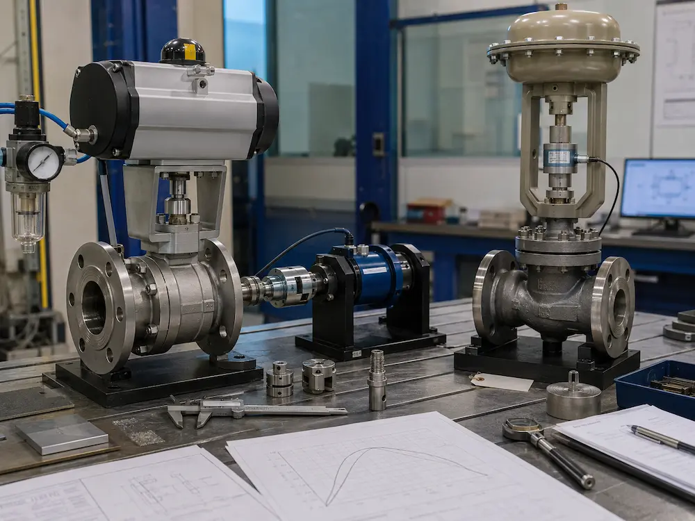
“Fail-safe” is incomplete unless the failure condition and required final valve position are stated.
The project should separately define behavior following:
- Loss of command signal
- Loss of communication
- Loss of electrical power
- Loss of instrument air
- Loss of hydraulic pressure
- Emergency shutdown command
- Internal actuator or accessory fault
Fail-Close
The valve moves to the closed position after the specified failure. This may be selected where stopping the process fluid reduces the identified process risk.
Fail-Open
The valve moves to the open position after the specified failure. This may be required where continued cooling, pressure relief, minimum flow or another process function must be maintained.
Fail-in-Place or Fail-Lock
The actuator holds or attempts to hold its last position. This behavior must be assessed against process forces, leakage through the control system and the duration of the failure.
The required position should be established by the process safety assessment, not by a general rule based only on valve type. See Fail-Close vs Fail-Open Valve for a focused comparison.
For pneumatic packages, the choice between spring-return and double-acting configurations is discussed in Single-Acting vs Double-Acting Actuators.
6. Select the Control and Feedback Architecture
The actuator must be compatible with both the required valve function and the plant control system.
On-Off Control
An on-off valve normally receives discrete open and close commands. A complete package may include:
- Open and close command inputs
- Open and closed limit switches
- Local and remote selector
- Position indication
- Fault or trip output
- Solenoid valve for pneumatic or hydraulic control
Inching or Jogging Control
Inching allows the valve to be moved in short increments. It is not automatically equivalent to accurate modulating control. The actuator, motor, gearing, controls and valve must be rated for the expected start-stop frequency.
Modulating Control
A modulating actuator repeatedly positions the valve between fully open and fully closed in response to a process command. The package may require:
- Analog or digital position command
- Position transmitter
- Positioner or actuator controller
- Required positioning accuracy and deadband
- Defined response after signal failure
- Suitable modulating duty rating
Common analog signals may include 4–20 mA or 0–10 V, but the project wiring diagram and control philosophy must confirm the actual input, output and failure logic. Command signal and position feedback are separate functions and should not be assumed to use the same signal type.
See Electric Valve Actuator Control Signals for signal and feedback selection details.
7. Confirm Duty Cycle, Operating Frequency and Speed
An actuator capable of moving a valve once during a factory test may still be unsuitable for the actual operating duty.
Provide the expected:
- Number of operations per hour, day or year
- Maximum consecutive starts
- Average and maximum running time
- Required opening and closing time
- On-off, inching or continuous modulating duty
- Expected periods in the fully open, closed or intermediate position
Operating speed should be selected according to process requirements. A faster actuator is not automatically better. Rapid valve movement can contribute to pressure surges, water hammer, unstable control or excessive mechanical impact. Conversely, an actuator that moves too slowly may not meet emergency isolation or process-response requirements.
For pneumatic and hydraulic systems, tubing size, control-valve flow capacity and exhaust restrictions can affect travel time. For electric actuators, motor speed, gear ratio, load and supply conditions must be considered.
8. Match the Actuator to the Installation Environment
Environmental suitability applies to the full actuator package, including the actuator housing, terminal compartment, solenoid valve, positioner, limit-switch box, cable glands, junction boxes and exposed tubing.
Confirm the following:
- Minimum and maximum ambient temperature
- Indoor, outdoor, exposed or sheltered installation
- Dust, rain, washdown, flooding or temporary immersion risk
- Marine, offshore, coastal or corrosive atmosphere
- Hazardous-area zone, division, gas group and temperature class
- Required ingress-protection or enclosure rating
- Coating system and external material requirements
- Vibration and seismic requirements where applicable
An ingress-protection rating describes protection against entry of solids and water. It does not by itself confirm hazardous-area suitability. Explosion-protection certification must match the applicable project classification and installation method.
For detailed environmental selection, see Electric Actuated Valve Enclosure Selection.
9. Verify the Mounting Flange, Bracket and Coupling
Actuator mounting is not complete merely because the bolt holes appear to match. The valve and actuator must be checked as a complete mechanical drive train.
For a part-turn package, verify:
- Valve mounting-flange designation and dimensions
- Actuator flange and bolt pattern
- Stem or shaft shape and dimensions
- Square, key, spline or other drive orientation
- Coupling bore, engagement depth and material
- Bracket height, rigidity and corrosion protection
- Actuator orientation and access to controls
- Alignment through the complete valve stroke
ISO 5211 provides standardized attachment dimensions for part-turn actuator connections, while ISO 5210 addresses multi-turn actuator attachments. Compliance with an interface standard does not eliminate the need to verify the intermediate bracket, coupling, stem load and package alignment.
See ISO 5211 Actuated Valve Mounting for a focused explanation of flange, drive and bracket alignment.
Misalignment can increase friction, produce uneven loading and accelerate wear. Additional examples are covered in Consequences of Misaligned Valve Actuators.
10. Select Accessories as Part of the Actuated Valve Package
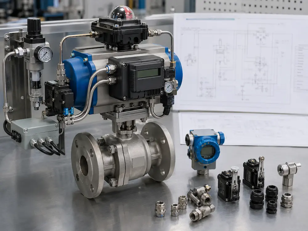
Accessories determine how the actuator receives commands, controls movement, reports position and reacts to abnormal conditions. They should be included in the package specification rather than added without a coordinated design.
| Accessory | Primary Function | Key Selection Information |
|---|---|---|
| Solenoid valve | Directs pneumatic or hydraulic supply | Voltage, porting, flow capacity, failure state and area certification |
| Limit-switch box | Reports open and closed positions | Switch type, quantity, contact rating, enclosure and cable entries |
| Positioner | Controls intermediate valve position | Input signal, actuator action, communication protocol, feedback and air capacity |
| Air filter regulator | Conditions and regulates pneumatic supply | Inlet pressure, outlet range, filtration, drainage and material |
| Speed controller | Adjusts opening or closing time | Required travel time, flow direction and fail-action influence |
| Position transmitter | Provides continuous position feedback | Output signal, accuracy, power supply and calibration range |
| Manual override | Allows local manual operation | Engagement method, access, interlock and safe operating procedure |
Accessory tubing, fittings, brackets, fasteners and cable entries should also match the environmental and material requirements of the project.
11. Actuator Selection by Typical Application
General Process On-Off Valves
Pneumatic rack-and-pinion or scotch-yoke actuators are frequently considered where instrument air is available and the valve requires repeated quarter-turn operation. Electric actuators are practical for distributed valves with lower operating frequency or without an air supply.
Control Valves
Control valves require coordinated selection of the valve body, trim, actuator, positioner and accessories. The actuator must provide sufficient thrust or torque throughout the control range and maintain the required positioning performance under changing process forces.
Review available industrial control valve configurations when the application requires continuous regulation rather than simple isolation.
Remote Pipeline Isolation
Electric actuators may suit stations with reliable electrical power and remote communication. Hydraulic, gas-hydraulic or pneumatic systems may be selected for high-output or emergency shutdown requirements. The decision should include available utility supply, communication architecture, required closing time and energy available after a station failure.
Emergency Shutdown Valves
An emergency shutdown package must be based on the approved shutdown philosophy. Required closing or opening time, stored energy, partial-stroke testing, voting logic, reset method and proof-test requirements should be specified by the responsible process and safety disciplines.
Power and Steam Systems
High-temperature steam and feedwater services require review of valve operating thrust or torque, thermal effects, stem packing friction, seating force, operating frequency and accessibility. Actuator location and bracket arrangement should protect sensitive components from excessive heat while maintaining alignment.
Water and Wastewater Systems
Electric multi-turn and part-turn actuators are widely considered for gates, butterfly valves and isolation valves where electrical infrastructure is available. Outdoor exposure, flooding risk, condensation, operating frequency and emergency manual operation should be defined.
12. Inspect and Test the Complete Valve–Actuator Assembly
Separate valve and actuator certificates do not prove that the assembled package performs correctly. Final inspection should verify the mechanical, control and failure functions after assembly.For an agreed pre-shipment verification sequence, review the valve Factory Acceptance Test checklist.
A project-specific inspection and test plan may include:
- Valve, actuator and accessory identification
- Mounting orientation and fastener verification
- Coupling engagement and alignment
- Full open-to-close functional stroke
- Direction of operation
- Opening and closing travel time
- Limit-switch and position-indicator adjustment
- Torque-switch or thrust-limit setting where applicable
- Control signal and position feedback verification
- Local, remote and manual-override operation
- Specified fail-action test
- Solenoid, positioner and accessory function
- Valve shell and seat tests according to the agreed valve standard
- Coating, preservation and cable-entry protection
For control valves, the actuator and required accessories form part of the complete ready-to-use valve assembly. Inspection scope should therefore address the assembled control valve rather than treating the actuator as unrelated equipment.
For the detailed setup and acceptance workflow, including mechanical release, zero and span, digital auto-calibration, intermediate travel checks, feedback and failure testing, use our Control Valve Positioner Calibration Guide.
Typical Documentation
- Valve and actuator data sheets
- Approved general arrangement drawing
- Actuator sizing calculation or selection sheet
- Valve torque or thrust data
- Wiring and terminal diagram
- Pneumatic or hydraulic schematic
- Accessory list and material specification
- Functional test report
- Valve pressure and leakage test report
- Hazardous-area certificates where required
- Installation, operation and maintenance manuals
13. Valve Actuator RFQ Checklist
For an accurate quotation, provide as much of the following information as available.
- Valve details: type, size, pressure class, body material, seat or trim material and connection.
- Process data: medium, design and operating pressure, differential pressure, temperature and flow direction.
- Valve movement: part-turn, multi-turn or linear.
- Required output: valve torque, thrust, stroke, number of turns and allowable stem load.
- Actuator preference: pneumatic, electric, hydraulic or open for engineering selection.
- Utility supply: minimum and maximum air or hydraulic pressure, or electrical voltage, phase and frequency.
- Control mode: on-off, inching, modulating or emergency shutdown.
- Fail position: fail-open, fail-close, fail-in-place or other defined action.
- Control signals: discrete, analog or digital communication requirements.
- Feedback: open/closed contacts, continuous position feedback and fault outputs.
- Operating time: required opening and closing time.
- Duty: operating frequency, starts per hour and modulating requirement.
- Site environment: ambient temperature, outdoor exposure, corrosion and ingress requirements.
- Hazardous area: classification, gas group, temperature class and required certification system.
- Accessories: solenoid, limit switches, positioner, air set, speed control, manual override or local control station.
- Inspection documents: drawings, calculations, certificates, reports and third-party inspection requirements.
When valve operating torque or thrust is not available, provide the complete valve and process data so the requirement can be reviewed before the actuator is selected.
14. Relevant Standards and Project References
The applicable standard depends on the valve type, actuator motion and project specification. Common references may include:
- ISO 5211 for part-turn actuator attachments
- ISO 5210 for multi-turn actuator attachments
- IEC 60534-1 for control valve terminology and general considerations
- IEC 60534-4 for control valve inspection and routine testing
Standards should not be listed as general product compliance unless the selected valve, actuator, interface and test scope have been reviewed against the applicable edition and project documents.
Valve Actuator Selection Guide: Final Engineering Check
The correct actuator is the one that operates the selected valve reliably under the actual process, utility and environmental conditions while meeting the required control and failure functions.
Before releasing an order, confirm all of the following:
- The actuator motion matches the valve movement.
- Torque or thrust is based on actual valve operating data.
- Output is adequate at the minimum available utility condition.
- The valve stem, shaft, coupling and gearbox will not be overloaded.
- The required behavior after each defined failure is documented.
- Control signals and feedback match the plant system.
- Duty, speed and operating frequency are suitable.
- All electrical and pneumatic accessories match the site classification.
- The mounting interface, bracket and coupling have been verified.
- The assembled valve package will undergo functional testing.
This complete-package approach is more reliable than selecting the actuator from valve size, power source or nominal output alone.
Need an Actuated Valve Package?
Send Vcore Valve the valve specification, process conditions, torque or thrust requirement, utility supply, fail position, control signals and site classification. We can review the valve, actuator, mounting and accessory configuration as one package.
Related Technical Resources
- Valve Actuator Torque Sizing: Break Torque, Running Torque and Safety Factor
- Electric Valve Actuator Control Signals
- Electric Actuated Valve Enclosure Selection
- ISO 5211 Actuated Valve Mounting
- Single-Acting vs Double-Acting Actuators
- Fail-Close vs Fail-Open Valve
- Manual vs Automatic Valve Selection
Frequently Asked Questions
How do I choose between a pneumatic and electric valve actuator?
Compare the available utility supply, required operating speed, duty, fail action, control interface and site environment. Pneumatic actuation is often practical where reliable instrument air is available and spring-return action or faster cycling is required. Electric actuation is frequently suitable where electrical power is available but instrument air is not.
When should a hydraulic valve actuator be selected?
A hydraulic actuator may be considered when the valve requires high torque or thrust, particularly for large pipeline valves or critical shutdown duties. The added hydraulic power, fluid-control and maintenance requirements must also be evaluated.
Can an actuator be selected only from the valve size?
No. Valve size alone does not determine the required actuator output. Selection should use confirmed valve torque or thrust under the actual differential pressure, temperature, seat material, media and operating conditions.
How much actuator safety factor should be used?
The required margin should follow the valve manufacturer’s data, actuator selection procedure and project specification. A universal percentage should not be applied without checking the valve torque profile, minimum utility supply and allowable stem or shaft load.
Does an electric actuator automatically fail-close during a power failure?
No. A conventional electric actuator cannot move after loss of power unless the package includes a suitable stored-energy or backup-power system. The required action after signal loss and after power loss must be specified separately.
Is a pneumatic actuator automatically explosion-proof?
No. Although the actuator mechanism may use compressed air, its solenoid valves, positioners, limit switches and other electrical accessories must still match the hazardous-area classification.
What information is required to quote an actuated valve?
Provide the valve type, size, pressure rating, materials, process conditions, required torque or thrust, utility supply, control mode, fail position, operating time, duty, environment, hazardous-area classification and required accessories.