Quick Summary
Pneumatic actuator air consumption is the normalized volume of compressed air used to move an actuated valve. Calculate it from the actuator chamber volume, absolute supply pressure, powered strokes per cycle and operating frequency. Then check a separate value—the airflow required during the specified stroke time—to size the solenoid valve, tubing, fittings and local air accessories.
- Use the actuator manufacturer’s chamber-volume or air-consumption data whenever it is available.
- Convert compressed chamber volume to free air using absolute, not gauge, pressure.
- Do not use average plant demand to select a solenoid valve: a two-second stroke can require far more instantaneous flow.
- Size at the minimum air pressure that can reach the actuator during operation, not only the compressor set pressure.
- Verify the completed valve package by measuring pressure at the actuator and timing both travel directions.
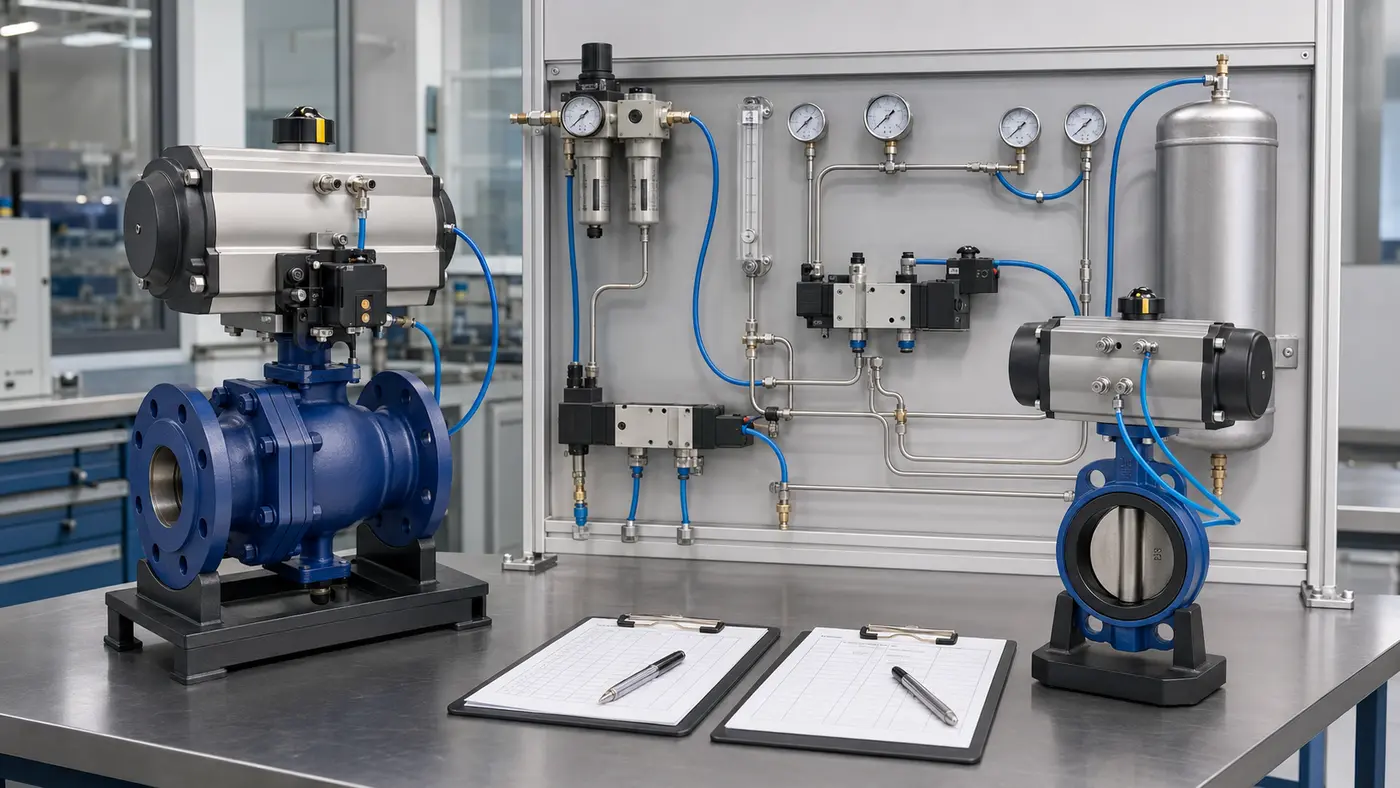
A pneumatic valve may operate only a few times per hour and still fail a two-second closing requirement. That is not a contradiction. The compressor may have enough total capacity, while the regulator, solenoid, tubing or exhaust path cannot deliver the required flow during the short movement.
This guide treats the actuator as part of an integrated valve package. The valve torque requirement determines actuator size; actuator size determines chamber volume; and chamber volume, pressure and travel time determine the air-supply system. If the actuator has not yet been selected, complete the valve actuator torque sizing first and confirm the mechanical interface using the ISO 5211 actuated valve mounting guide.
Three Numbers That Answer Three Different Questions
“How much air does this actuator need?” is incomplete unless the required output is defined. A practical calculation should report all three values below.
| Calculated value | Typical unit | What it is used for |
|---|---|---|
| Normalized air per stroke or cycle | NL/stroke, NL/cycle, SCF/cycle | Comparing actuator consumption and estimating stored-air requirements |
| Average air demand | NL/min, Nm³/h, SCFM | Compressor capacity, plant-wide load and operating-cost estimates |
| Required stroke flow | NL/min or SCFM during travel | Solenoid valve, regulator, tubing, fittings, quick exhaust and booster sizing |
Confusing these values causes predictable errors. Multiplying air per cycle by cycles per minute gives an average demand, but that average does not describe a two-second opening event. Conversely, selecting a compressor from the peak flow of every valve can greatly overstate plant demand when the valves do not move simultaneously.
Define the Calculation Boundary Before Using a Formula
Decide what the calculation includes. The actuator datasheet may state only the internal chamber consumption. The installed package also contains tubing and accessory cavities that are pressurized and exhausted. A project calculation should therefore record:
- actuator type: double acting or spring return;
- actuator model and chamber volume for each powered direction;
- minimum and maximum pressure available at the actuator inlet;
- required opening and closing times;
- normal, peak and emergency cycle frequency;
- tube internal diameter and length;
- solenoid, regulator, flow-control, silencer and quick-exhaust arrangement;
- air temperature and the project’s normal-volume reference conditions;
- leakage allowance and any future operating allowance required by the project.
Rack-and-pinion and scotch-yoke actuators have internal geometry that is not represented accurately by a simple external cylinder calculation. The manufacturer’s air-volume table is the preferred input. If the manufacturer gives “air consumption per cycle” at a stated pressure, confirm whether that value is normalized free air and whether it represents one stroke or a complete open-and-close cycle.
Step 1: Convert Chamber Volume to Normalized Air
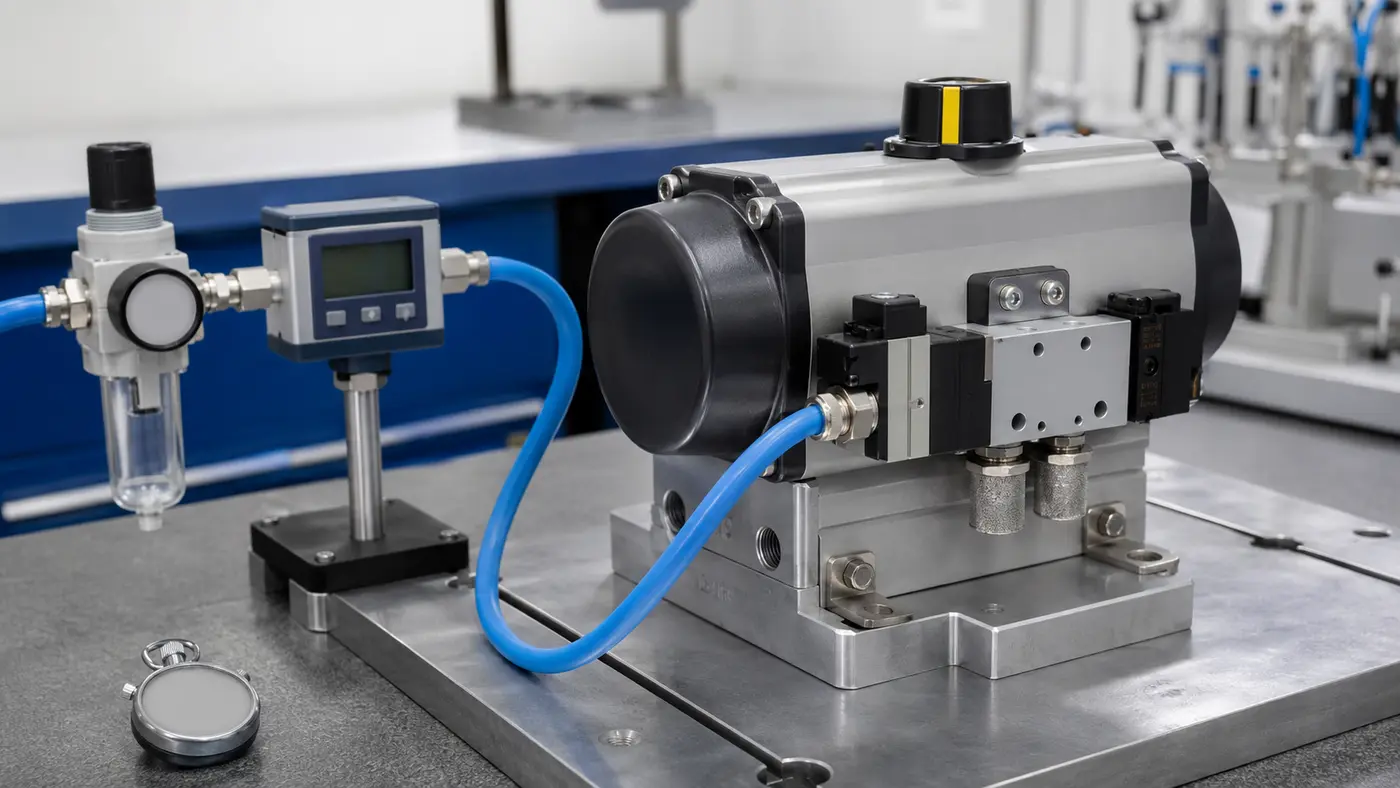
A 2.8 L actuator chamber does not consume only 2.8 normal liters when it is filled to 6 barg. The gas inside the chamber is compressed. For an engineering estimate based on the ideal-gas relationship:
VN = Vchamber × (Pabs,supply / Pabs,normal) × (Tnormal / Tsupply)
If the reference and supply temperatures are similar, the temperature ratio is often treated as approximately 1:
VN ≈ Vchamber × (pg + patm) / patm
Where:
- VN = normalized or free-air volume;
- Vchamber = pressurized actuator chamber volume;
- pg = supply gauge pressure;
- patm = local atmospheric pressure;
- Pabs = absolute pressure;
- T = absolute temperature in kelvin.
Why absolute pressure matters: 6 barg is approximately 7.013 bar absolute when atmospheric pressure is 1.013 bar. Dividing 6 by 1.013 omits the atmosphere and understates the normalized air volume.
If Only Cylinder Dimensions Are Available
For a conventional linear piston cylinder, geometric volume can be estimated from bore, rod diameter and stroke:
Cap-end volume = πD²s / 4
Rod-end volume = π(D² − d²)s / 4
Here, D is piston bore, d is rod diameter and s is stroke. Add end-clearance volume if known. Do not apply these equations to a quarter-turn rack-and-pinion or scotch-yoke actuator unless the manufacturer specifically provides the internal dimensions needed for that model.
Step 2: Count the Powered Strokes Correctly
Double-Acting Actuator
A double-acting actuator uses compressed air to open and to close. If the two chamber volumes differ, calculate them separately:
VN,cycle = VN,open + VN,close
One cycle means one complete opening and one complete closing. Some catalogs use “operation” to mean a single stroke, so the datasheet definition must be checked.
Spring-Return Actuator
A spring-return actuator normally uses compressed air in only one direction; stored spring energy drives the fail direction. Its per-cycle compressed-air consumption is therefore based on the powered chamber fill, plus connected accessory and tubing volume. It does not mean the actuator is automatically smaller or more efficient: the pneumatic side must also overcome the spring load, which often increases actuator size.
The operating choice should follow the required failure position and safety philosophy, not air consumption alone. For the functional differences, see single-acting versus double-acting actuators.
Worked Example: One Cycle Uses 34.6 NL, but Opening Needs 582 NL/min
Consider a double-acting quarter-turn actuator with the following manufacturer data and service requirements:
- opening chamber volume: 2.8 L;
- closing chamber volume: 2.2 L;
- supply pressure at the actuator: 6 barg;
- atmospheric pressure: 1.013 bar;
- normal operating rate: 12 complete cycles per hour;
- required opening time: 2 seconds;
- required closing time: 2 seconds;
- temperature correction omitted for this preliminary estimate because reference and supply temperatures are assumed similar.
1. Calculate the Pressure Ratio
Pressure ratio = (6 + 1.013) / 1.013 = 6.92
2. Calculate Normalized Air per Stroke
Opening air = 2.8 × 6.92 = 19.4 NL
Closing air = 2.2 × 6.92 = 15.2 NL
3. Calculate Air per Complete Cycle
Air per cycle = 19.4 + 15.2 = 34.6 NL/cycle
4. Calculate Average Plant Demand
Average demand = 34.6 × 12 = 415 NL/h = 6.9 NL/min
5. Calculate the Flow Required During Each Stroke
Opening flow = (19.4 / 2) × 60 = 582 NL/min
Closing flow = (15.2 / 2) × 60 = 456 NL/min
The compressor sees only 6.9 NL/min as the long-term average for this valve, but the opening air path must deliver approximately 582 NL/min during movement before additional allowance and pressure losses are considered. This is why selecting the solenoid from 6.9 NL/min would be a serious mistake.
| Result | Value | Selection decision |
|---|---|---|
| Air per cycle | 34.6 NL/cycle | Consumption and stored-air estimate |
| Average demand | 6.9 NL/min | Plant air-load estimate |
| Opening stroke flow | 582 NL/min | Opening supply-path flow check |
| Closing stroke flow | 456 NL/min | Closing supply/exhaust-path flow check |
These are idealized calculation results, not final component ratings. Tubing dead volume, valve flow curves, pressure drop, air temperature, leakage and the project-approved design allowance must still be considered.
Pressure Couples Air Consumption to Valve Torque
Increasing actuator supply pressure normally increases actuator torque, but it also increases the normalized air used for each chamber fill. The usable pressure is the pressure available at the actuator while it is moving, not the no-flow pressure shown at the compressor or wall regulator.
Check two ends of the pressure range:
- Minimum dynamic pressure: the actuator must produce sufficient torque after regulator, solenoid, fitting and tubing losses.
- Maximum possible pressure: the valve stem, coupling, bracket and gearbox must not be overloaded if the regulator is set high or fails.
Valve break torque can exceed running torque, especially after long static periods, at low temperature, with dry media or under full differential pressure. An actuator that moves freely during an unloaded workshop test may still stall in service. Torque sizing and air-flow sizing therefore need to use the same pressure assumptions.
The Air Path, Not the Actuator Port, Often Sets Cycle Time
The calculated stroke flow must pass through every restriction between the header and actuator—and through the exhaust path on the opposite chamber. Review the complete chain:
Plant header → isolation valve → filter/regulator → solenoid valve → fittings → tubing → speed control → actuator port → exhaust fitting or silencer
Solenoid Valve
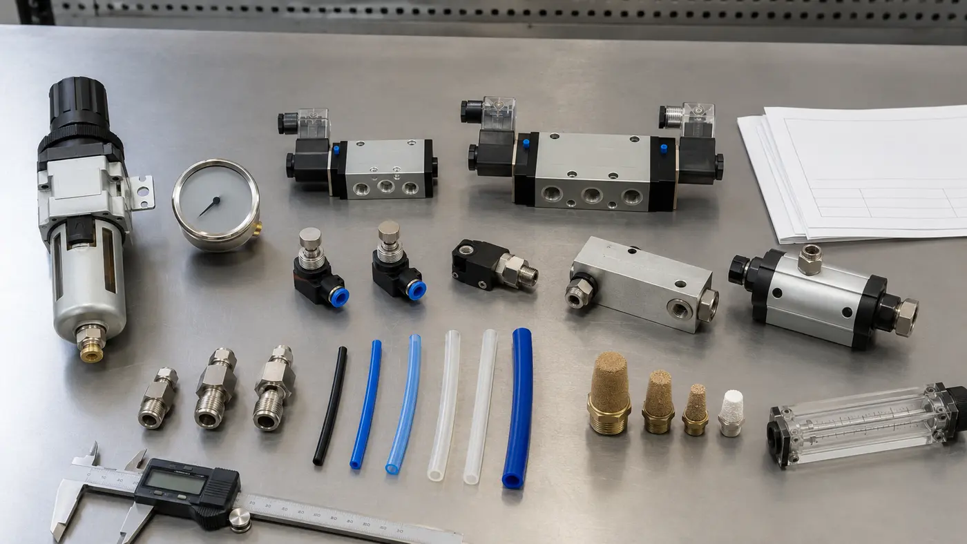
Select the solenoid configuration for the actuator and failure action—commonly 5/2 for double acting and 3/2 for spring return—then use the manufacturer’s flow curve, Cv, Kv or standardized flow rating at the actual inlet and outlet conditions. A nominal port size alone does not define usable airflow.
Regulator and Filter
A regulator can hold the correct static pressure yet droop during a fast stroke. Check its flow curve and ensure the filter element is sized and maintained for the peak demand. Pressure should be observed upstream and downstream during movement when diagnosing slow travel.
Tubing and Fittings
Use tube internal diameter—not only outside diameter—and include length, bends, tees, push-in fitting bores and exhaust restrictions. Long tubing on a remote valve both adds volume and increases pressure drop. Placing the solenoid near the actuator can shorten the final flow path, subject to electrical, environmental and maintenance requirements.
Speed Controls, Silencers and Exhaust
Meter-out flow controls are useful for stable travel, but an excessively closed control creates slow or uneven movement. Contaminated exhaust silencers are a common hidden restriction. A quick-exhaust valve or volume booster may improve response where the control philosophy permits it, but it should be selected and tested as part of the complete circuit rather than added as a generic cure.
Screening a Local Air Receiver for Emergency Operation
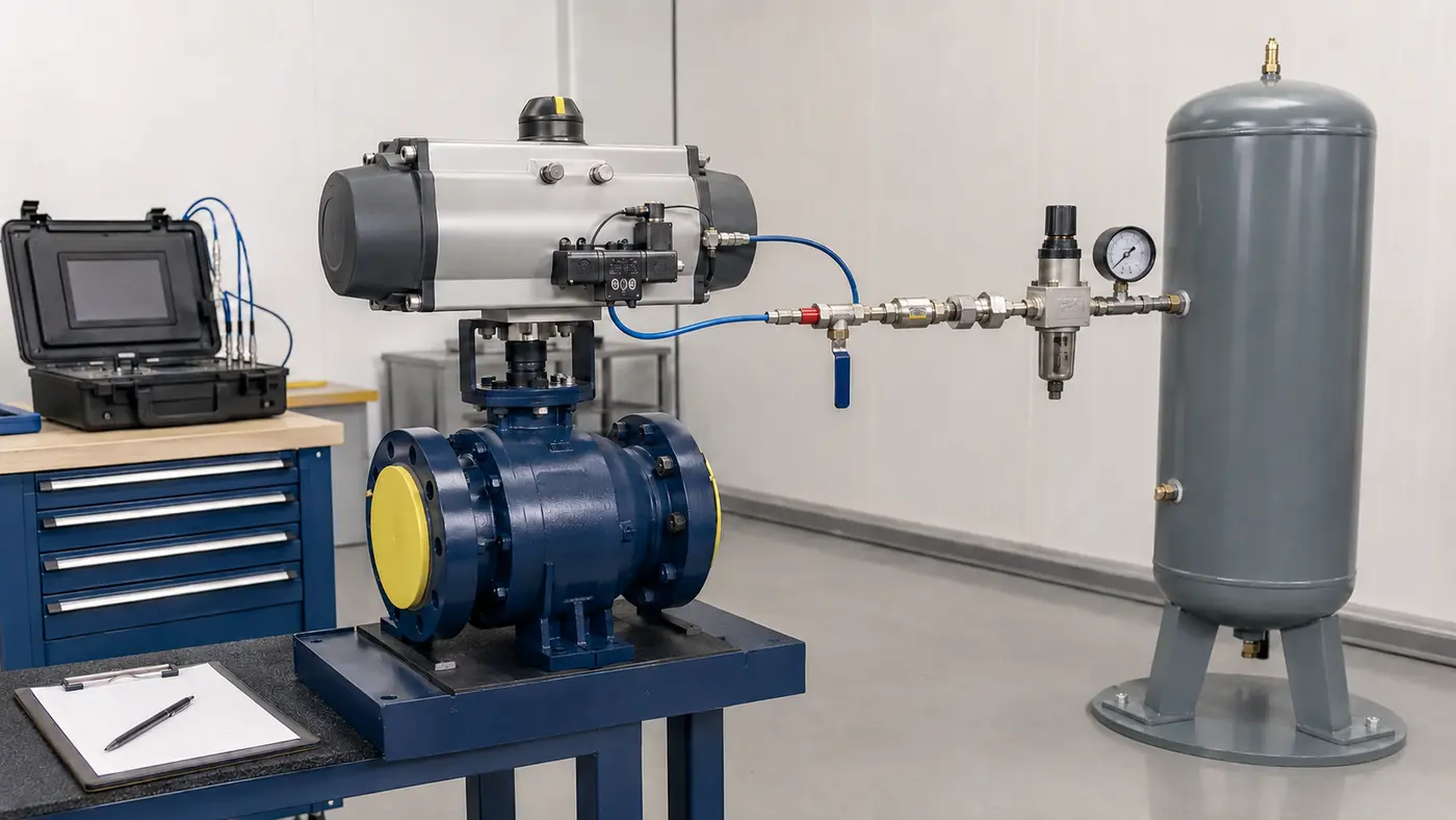
A local receiver may be required when the plant header cannot support peak flow, when the valve is remote, or when one or more movements must be completed after air-supply loss. For a preliminary isothermal screening calculation:
Vreceiver ≈ VN,required × Patm / (P1,abs − P2,abs)
Where P1 is initial receiver pressure and P2 is the lowest allowable receiver pressure after operation. Both must be absolute pressures. The minimum final pressure must still provide sufficient actuator torque after the regulator and flow-path losses.
Using the example’s 19.4 NL opening stroke, an 8 barg receiver that may fall to 5 barg gives:
Vreceiver ≈ 19.4 × 1.013 / [(8 + 1.013) − (5 + 1.013)] = 6.55 L
This 6.55 L result is an ideal preliminary value for one powered stroke. It does not include line volume, leakage, regulator behavior, temperature change, reserve, repeated emergency strokes or code requirements. Apply the documented project allowance, choose an appropriate standard receiver and have the final pneumatic system reviewed for pressure-vessel and safety requirements.
Air Quality Is Part of Reliability
Insufficient flow is not the only air-supply problem. Water, oil and particles can affect seals, solenoids, positioners and exhaust components. ISO 8573-1:2010 defines compressed-air purity classes for particles, water and oil. The required class for a valve package must come from the actuator and accessory manufacturers plus the project specification; it should not be assumed from the standard title alone.
Also verify the permitted dew point at the lowest ambient temperature. Condensate that freezes in an outdoor solenoid or exhaust path can prevent the required safety movement even when the room-temperature air-consumption calculation is correct.
Symptoms That Point to a Flow or Air-Volume Problem
| Observed symptom | Likely checks |
|---|---|
| Correct static pressure, but slow travel | Dynamic pressure droop, regulator flow, solenoid Cv/Kv, tubing ID, blocked silencer |
| Opening is slower than closing | Different chamber volumes, asymmetric torque, one flow control, one exhaust restriction |
| Valve stalls near the seat | Break/end torque, minimum dynamic pressure, mechanical alignment, seat condition |
| First cycle is normal, repeated cycles slow down | Header recovery, receiver recharge, regulator capacity, compressor duty |
| Calculated time is short, installed time is long | Uncounted tube volume, restrictive fittings, catalog rating conditions, exhaust path |
| Air use is higher than the calculation | External leakage, internal seal bypass, excessive pressure, frequent cycling, accessory bleed |
If a mechanically aligned package repeatedly binds or travels unevenly, also inspect the bracket, coupling and shaft alignment. The consequences are discussed in misaligned pneumatic valve actuators.
Information to Put on the Sizing Sheet or RFQ
A useful actuator air-supply request should include enough information for the valve, actuator and accessories to be checked together:
- valve type, size, pressure class and process medium;
- maximum differential pressure and required valve torque or thrust;
- actuator make, model, action and spring set where applicable;
- manufacturer chamber volume or stated air consumption and rating conditions;
- minimum/normal/maximum air pressure at the valve location;
- opening and closing time, including tolerance;
- normal cycle rate, peak cycle rate and simultaneous valve movements;
- solenoid function, voltage, flow rating and mounting method;
- tube material, internal diameter, length and fitting arrangement;
- ambient range, enclosure/hazardous-area requirement and specified air quality;
- fail position and number of movements required after air-supply loss;
- acceptance criteria for leakage, travel time and position feedback.
For butterfly-valve applications, the pneumatic butterfly valve guide provides additional package-selection context. Available valve families can also be reviewed under ball valves, butterfly valves and control valves.
Verify the Completed Valve Package
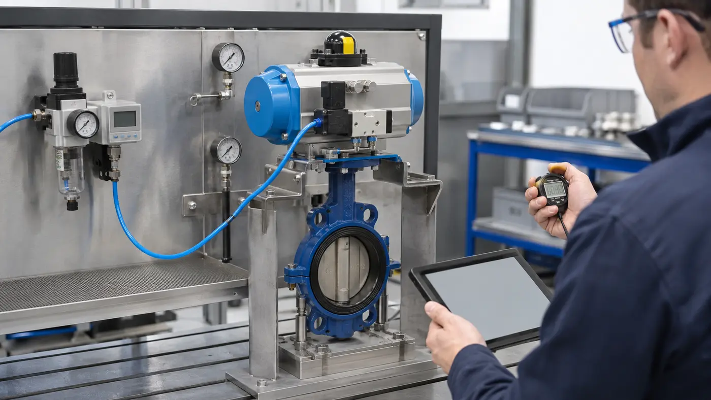
The final proof is an integrated test. Use the specified air pressure and final accessory arrangement, then:
- record static pressure before movement;
- record minimum pressure at the actuator during opening and closing;
- measure both stroke times over repeated cycles;
- confirm open and closed position indication;
- check external leakage at tubes, fittings and accessory ports;
- confirm the required fail action by simulating loss of power and/or air according to the approved test procedure;
- if a receiver is fitted, verify the required number of movements from minimum specified stored pressure;
- document regulator setting, speed-control position and test temperature.
For a project-specific package, send the valve duty, differential pressure, available air-pressure range, required travel time, cycle rate and failure action through the contact page. That information allows the torque check and pneumatic flow check to be completed as one integrated selection.
Frequently Asked Questions
What is pneumatic actuator air consumption?
Pneumatic actuator air consumption is the normalized volume of compressed air used to complete a powered stroke or operating cycle. It depends mainly on actuator chamber volume, absolute supply pressure, actuator action and operating frequency.
How much air does a double-acting actuator use per cycle?
A double-acting actuator uses air for both opening and closing. Calculate the normalized air for each chamber at the actual supply pressure, then add the two results. Check the manufacturer’s definition because some datasheets report one stroke while others report a complete cycle.
Why must absolute pressure be used in an air-consumption calculation?
Gas-volume conversion is based on absolute pressure. Gauge pressure excludes atmospheric pressure, so using it directly understates the amount of free air compressed into the actuator chamber.
Why is average compressor demand much lower than the required solenoid flow?
Average demand spreads consumption across the full time between cycles. Solenoid and tubing flow must deliver the stroke volume during the much shorter valve travel time, so their required instantaneous flow can be many times higher.
Does a spring-return actuator use compressed air in both directions?
Normally no. Compressed air powers one direction and the spring powers the fail direction. The powered chamber, connected tubing and accessories consume air, while actuator sizing must also account for the torque required to compress the spring.
How do I size an emergency air receiver for a pneumatic valve?
Define the normalized air required for all emergency strokes, the receiver’s initial pressure and the lowest pressure that still provides adequate actuator torque. Calculate a preliminary volume from the usable absolute-pressure range, then add the documented project allowance and validate regulator flow, leakage, temperature and pressure-vessel requirements.
Technical References
- Festo air-consumption calculator — calculation inputs include cylinder type, size, stroke, operating pressure and cycles.
- Rotork RC200 pneumatic actuator documentation — manufacturer air-consumption and operation-time data are provided for actuator selection.
- Emerson ASCO solenoid example — illustrates directional-valve function and Cv/Kv flow data used in accessory selection.
- Rotork YT-315 volume booster — an example of an accessory intended to reduce actuator response time where the circuit requires additional flow capacity.
- ISO 8573-1:2010 — compressed-air purity classes for particles, water and oil.