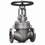
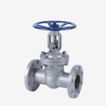
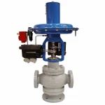
Quick Answer: Valve stem thrust calculation is not the same as quarter-turn valve torque sizing. For a rising-stem gate or globe valve, calculate the maximum opening and closing thrust separately by considering differential-pressure load, seat or wedge load, packing friction, stem and guide friction, component weight where relevant, and any spring force. Then confirm stroke, stem lead, speed, mounting interface, allowable valve stem load and actuator thrust limit. Use the valve manufacturer’s certified thrust data whenever it is available; simplified equations are screening tools, not a substitute for the approved valve-and-actuator calculation.
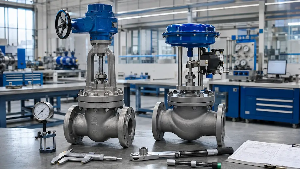
Valve stem thrust calculation determines the linear force required to open, move and close a rising-stem valve under its specified service conditions. It is essential for motor-operated gate valves, actuated globe valves and many sliding-stem control valves. Selecting an actuator from valve size or motor power alone can result in failure to unseat, insufficient shutoff force, overloaded stems, damaged seats or incorrect torque-switch settings.
This engineering worksheet explains how the load is assembled, why gate and globe valves require different treatment, and how thrust can be related to stem-nut torque. It complements our valve actuator torque sizing guide, which focuses mainly on quarter-turn ball and butterfly valves.
Start with the Correct Output: Torque or Thrust?
| Valve / Motion | Primary Sizing Output | Additional Checks |
|---|---|---|
| Ball valve or butterfly valve | Rotary torque, normally in N·m | Break, running, closing and maximum allowable stem torque |
| Rising-stem gate valve | Linear stem thrust, normally in N or kN | Stem-nut torque, turns, travel, speed, buckling and maximum allowable thrust |
| Globe on-off valve | Linear stem thrust | Flow direction, plug unbalance, seat load, packing friction and stroke |
| Sliding-stem control valve | Actuator force across the full signal and travel range | Dynamic unbalance, spring force, packing, shutoff class and available air pressure |
A multi-turn electric actuator produces rotary output, while a threaded stem nut or linear thrust unit converts that rotation into axial movement. Therefore, the valve supplier must know both the required stem thrust and the torque that the actuator or gearbox must deliver through the selected drive arrangement.
The Stem Thrust Load Ledger
A useful first-pass model is:
Frequired = Fpressure + Fseat/wedge + Fpacking + Fstem/guide ± Fweight ± Fspring
The signs and timing are important. Not every force reaches its maximum at the same valve position. Calculate at least the critical opening and closing cases separately rather than adding every maximum into one unrealistic number.
| Load Component | What Creates It | Data Needed |
|---|---|---|
| Differential-pressure load | Pressure acting on the effective unbalanced area | Maximum differential pressure, flow direction and effective area |
| Seat or wedge load | Required sealing stress, wedge action or plug-to-seat contact | Valve design, seat geometry, shutoff requirement and manufacturer data |
| Packing friction | Stem contact with compressed packing rings | Stem diameter, packing material, gland load and condition |
| Stem, guide and bearing friction | Thread, guide, bearing and alignment losses | Stem thread, lubrication, nut material, guide design and alignment |
| Component weight | Weight of a vertical stem, gate, plug or connected parts | Orientation and moving-component mass |
| Spring force | Actuator return spring or valve balancing spring | Spring rate, preload, travel and fail direction |
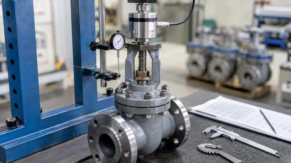
Gate Valve Thrust: Calculate Opening and Closing Separately
A wedge gate valve under differential pressure is not correctly represented by one universal formula. Pressure pushes the gate against the downstream seat, creating sliding friction during initial opening. Wedge angle, seat geometry, surface condition, guide friction, packing load and thermal effects can materially change the required thrust.
Critical Gate Valve Positions
- Unseating from fully closed: commonly the highest opening load because the gate may be wedged and pressure-loaded against a seat.
- Running through travel: load may fall after the gate separates from the seat, but packing and guide friction remain.
- Approaching full open: check backseat contact only if the valve is designed and specified to use it.
- Final closing and seating: sufficient thrust is required for shutoff, but excessive thrust can damage the wedge, seats, stem or actuator drive.
For preliminary screening, differential pressure multiplied by an effective projected area can help establish the scale of hydraulic loading:
Fhydraulic,screen = ΔP × Aeffective
However, Aeffective is not automatically the full nominal bore area, and the resulting force is not automatically the required stem thrust. A gate valve calculation must translate hydraulic side load into seat friction and axial stem load using the actual wedge and seat geometry. Obtain the valve manufacturer’s opening, running and closing thrust values whenever possible.
Gate Valve Data That Should Come from the Manufacturer
- Maximum required opening or unseating thrust at design differential pressure
- Maximum running thrust in both directions
- Required closing or seating thrust
- Maximum allowable stem thrust in tension and compression
- Maximum allowable actuator or stem-nut torque
- Stem diameter, thread form, pitch or lead, and number of starts
- Full travel, total turns and required operating time
Globe Valve Thrust: Use Effective Unbalanced Area
For an unbalanced globe valve plug, the basic hydraulic force is:
Funbalance = ΔP × Aunbalanced
For a simple circular unbalanced area:
A = πd² / 4
The force direction depends on flow direction and whether the design is flow-to-open or flow-to-close. Balanced plugs reduce the effective unbalanced area, but they do not make it zero; seal friction and residual pressure area must still be considered. For a control valve, calculate the actuator force across the full travel range because differential pressure, plug area, spring force and packing friction may change with position.
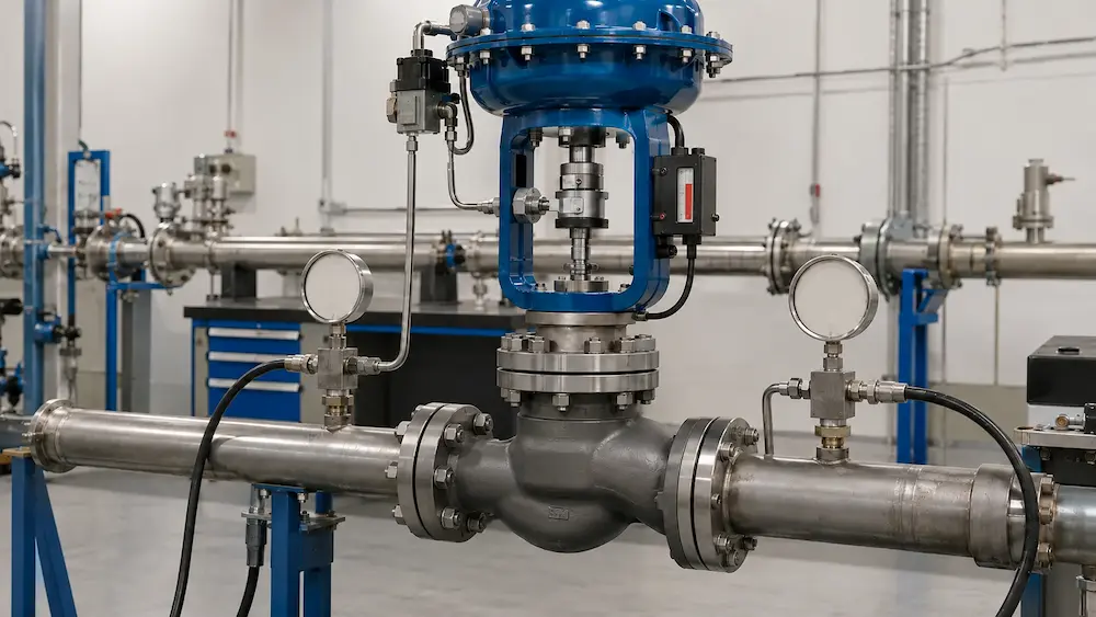
Illustrative Globe Valve Screening Calculation
Assume the following preliminary data for an unbalanced globe valve:
- Effective unbalanced diameter: 80 mm
- Maximum differential pressure: 1.6 MPa
- Estimated packing and guide friction: 2.5 kN
- Required seating load supplied by the valve manufacturer: 6.0 kN
Step 1 — Convert diameter to area:
A = π × 0.08² / 4 = 0.005027 m²
Step 2 — Calculate hydraulic unbalance:
Funbalance = 1,600,000 × 0.005027 = 8,043 N ≈ 8.04 kN
Step 3 — Build separate load cases:
| Load Case | Illustrative Calculation | Result Before Margin |
|---|---|---|
| Opening against adverse pressure | 8.04 kN hydraulic + 2.50 kN friction | 10.54 kN |
| Closing and seating, if hydraulic force opposes closing | 8.04 kN hydraulic + 2.50 kN friction + 6.00 kN seating | 16.54 kN |
This example is intentionally simplified. Before selecting an actuator, confirm flow direction, whether the full pressure drop can exist at shutoff, actual plug balance, packing data, seat-load requirement, spring force, required fail action and the actuator’s available force at the minimum air-supply pressure or worst electrical condition.
Convert Required Thrust to Stem-Nut Torque
When a multi-turn actuator rotates a stem nut, a useful efficiency-based relationship is:
T = (F × L) / (2π × η)
Where:
- T = stem-nut input torque, N·m
- F = axial stem thrust, N
- L = stem lead, metres per revolution
- η = overall screw-drive efficiency
Lead is the axial travel per revolution. For a single-start thread, lead equals pitch. For a multi-start thread, lead equals pitch multiplied by the number of starts. Efficiency depends on thread form, mean diameter, friction, nut material, lubrication, bearings and load direction. Do not assume the same efficiency for a new lubricated assembly and an aged dry stem.
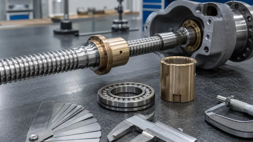
Illustrative Gate Valve Torque Conversion
Assume the valve manufacturer states that the maximum required stem thrust is 85 kN. The stem lead is 8 mm per revolution and the verified drive efficiency for the selected stem-nut arrangement is 0.30.
T = (85,000 × 0.008) / (2π × 0.30) = 361 N·m
If the project-approved sizing margin is 25% for this specific calculation:
Tselection = 361 × 1.25 = 451 N·m
The result does not authorize selecting an actuator only by finding the next model above 451 N·m. The selected assembly must also satisfy required and allowable thrust, stem acceptance, mounting flange, output speed, duty class, number of turns, ambient conditions, electrical supply and valve overload limits.
Safety Margin Is Not Permission to Overload the Valve
A sizing margin accounts for defined uncertainty such as friction variation, wear, temperature and supply fluctuation. It must be agreed for the valve, actuator and service. Larger is not automatically safer.
The final selection must satisfy both inequalities:
Available actuator thrust ≥ Required valve thrust with approved margin
Maximum transmitted thrust ≤ Allowable valve, stem, nut, yoke and mounting load
An oversized actuator may bend a stem, overload a threaded nut, deform a yoke, crush a seat or produce excessive seating stress. Electric actuator torque and limit switches must be set according to the approved valve requirement. Pneumatic actuator force must be checked at minimum available supply pressure, while maximum supply pressure must be checked against overload limits.
Stem Buckling and Tension Checks
A long rising stem loaded in compression can fail by buckling before the material reaches its simple compressive yield limit. This is particularly important for large valves, long strokes, stem extensions and unsupported stems. The stem supplier should check effective unsupported length, end conditions, root diameter, material properties, thread stress concentration and the required design factor.
Opening may place the stem in tension while closing may place it in compression, or vice versa depending on the valve and drive arrangement. Record the allowable load in both directions instead of using one unsigned number.
Actuator Sizing Worksheet
| Worksheet Item | Opening Case | Closing Case |
|---|---|---|
| Maximum differential pressure | ____ bar / MPa | ____ bar / MPa |
| Hydraulic / unbalanced load | ____ kN | ____ kN |
| Seat or wedge load | ____ kN | ____ kN |
| Packing, guide and stem friction | ____ kN | ____ kN |
| Weight and spring effects | ____ kN | ____ kN |
| Required thrust before margin | ____ kN | ____ kN |
| Approved sizing margin | ____ % | ____ % |
| Selected required thrust | ____ kN | ____ kN |
| Maximum allowable valve thrust | ____ kN | ____ kN |
Final Selection Checks Beyond the Calculation
- Valve function: isolation, throttling, emergency duty or modulating control
- Travel and turns: actual valve stroke divided by stem lead
- Operating time: actuator output speed matched to required travel time
- Duty classification: open-close, inching, positioning or modulating frequency
- Mounting interface: flange, drive form, stem diameter, stem rise and thrust-taking arrangement
- Fail action: fail-open, fail-close, fail-in-place or stored-energy requirement
- Power source: minimum pneumatic/hydraulic pressure or electrical voltage and frequency
- Environment: enclosure, hazardous area, ambient temperature, corrosion and ingress protection
- Controls: torque switch, limit switch, positioner, travel feedback and local manual override
- Overload protection: settings below the weakest allowable valve-train limit
For multi-turn actuator attachments, ISO 5210:2026 addresses flange and driving-component dimensions and gives reference torque and thrust values for the specified interfaces. It does not replace the valve-specific operating-load calculation. Electric actuator requirements should also be reviewed against the project specification and applicable standards such as ISO 22153.
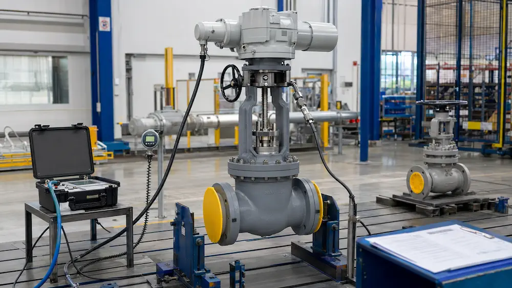
Information to Include in an RFQ
To size an actuated gate, globe or control valve, send the following information with the inquiry:
- Valve type, size, pressure class, material and end connection
- Medium, design and operating pressure, temperature and differential pressure
- Maximum shutoff differential pressure and flow direction
- Required leakage or shutoff class
- Stem diameter, thread form, pitch/lead, number of starts and full travel if an existing valve is being automated
- Required opening, running and closing thrust or torque from the valve manufacturer
- Maximum allowable stem thrust and torque
- Required operating time, duty cycle and starts per hour
- Power supply or minimum/maximum instrument-air pressure
- Fail action, control signal, feedback, hazardous-area and enclosure requirements
Vcore Valve can review the valve and actuator as one assembly for gate valves, globe valves and control valves. For quarter-turn mounting and alignment, also review our ISO 5211 actuated valve mounting guide. To request a project review, send the valve datasheet and actuator requirements to Vcore Valve.
Frequently Asked Questions About Valve Stem Thrust Calculation
What is valve stem thrust?
Valve stem thrust is the axial force transmitted through a valve stem to open, move, close or seat the valve closure member. It is normally expressed in newtons or kilonewtons.
Can actuator torque be converted directly into valve stem thrust?
It can be related through the stem lead and drive efficiency, but a reliable conversion also requires the thread form, friction, lubrication, nut and bearing design. The actuator’s published torque value alone is not enough.
Why must gate valve opening and closing thrust be calculated separately?
The critical loads occur at different positions. Unseating may require high force because of wedging and differential-pressure seat friction, while final closing requires controlled seating force. The maximum in one direction may not match the other.
Is differential pressure multiplied by bore area the final actuator thrust?
No. It is only a hydraulic-force screening calculation unless the effective area and load path are defined for the actual valve design. Seat friction, wedge geometry, packing, guides, stem thread and allowable loads must also be considered.
What safety factor should be used for valve actuator thrust?
There is no universal factor for every valve and service. The margin should be agreed from the valve manufacturer’s data, project specification, service severity, friction uncertainty, supply conditions and actuator duty. It must not cause the maximum transmitted thrust to exceed the valve’s allowable load.
Which standard covers multi-turn actuator attachment to valves?
ISO 5210:2026 specifies requirements for multi-turn actuator attachments, including flange and driving-component dimensions and reference torque and thrust values. Valve-specific operating thrust must still be calculated or supplied by the valve manufacturer.
Technical References
- ISO 5210:2026 — Industrial valves — Multi-turn actuator attachments
- ISO 22153:2020 — Electric actuators for industrial valves — General requirements
- AUMA — Multi-turn actuators and linear thrust units for gate and globe valve automation
- Emerson — Control Valve Handbook
- Rotork — Multi-turn gearbox torque and thrust application data
Practical takeaway: determine the valve’s required and allowable thrust first, evaluate opening and closing as separate load cases, and only then select the actuator, stem nut, gearbox and settings. The correct assembly must move the valve under worst-case conditions without exceeding any valve-train limit.