When a quotation states that a valve and actuator are “ISO 5211 compatible,” it can sound as if the mounting question has already been solved. In practice, that statement is only the beginning of the compatibility check.
The current ISO 5211:2026 standard covers the attachment of part-turn actuators, with or without gearboxes, to industrial valves. It specifies flange dimensions, relevant driving-component dimensions and reference torque values for interfaces and couplings. However, ISO explicitly places the attachment of an intermediate support outside the scope of ISO 5211. A separate mounting kit, adapter or bracket therefore still requires engineering verification.
This distinction matters for complete electric and pneumatic actuated valve packages. A matching flange code cannot compensate for an undersized actuator, a weak coupling, insufficient stem engagement or an off-center bracket. Those errors may appear only during commissioning—or after the valve has been operating under pressure for months.
What Does ISO 5211 Cover?
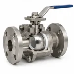
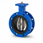
ISO 5211 applies to part-turn industrial valves, normally those whose operating member rotates through approximately 90 degrees. Typical examples include:
- Ball valves
- Butterfly valves
- Plug valves
- Part-turn dampers and special valves
The interface is commonly identified by flange designations such as F03, F04, F05, F07, F10 and larger sizes. The designation relates to defined attachment geometry. Buyers should not treat the code as a universal statement of allowable valve torque or actuator output. The selected valve drawing, actuator drawing and applicable standard edition remain the controlling documents.
| ISO 5211 helps standardize | Still requires project verification |
|---|---|
| Attachment flange dimensions | Actual valve operating torque under service conditions |
| Relevant actuator driving-component dimensions | Actuator output torque, duty and safety factor |
| Reference interface and coupling torque values | Mounting-kit design, material and stiffness |
| A common dimensional language between suppliers | Stem engagement, centerline alignment and clearances |
| Part-turn actuator-to-valve attachment requirements | Control signal, enclosure, hazardous-area and fail-position requirements |
For complete part-turn actuated valve packages, ISO 5115:2023 is also relevant because it addresses design considerations and responsibilities for the valve, actuator and mounting kit supplied as a package.
Why the Flange Code Alone Is Not Enough
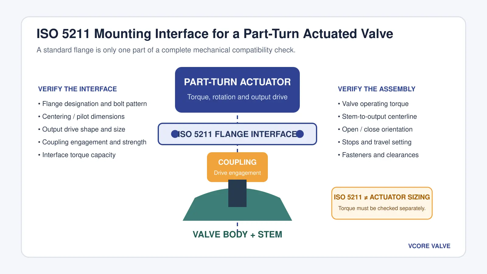
Two components can carry the same nominal ISO 5211 flange designation and still be unsuitable as an assembly. Compatibility depends on the complete path that transmits torque from the actuator to the valve closure member.
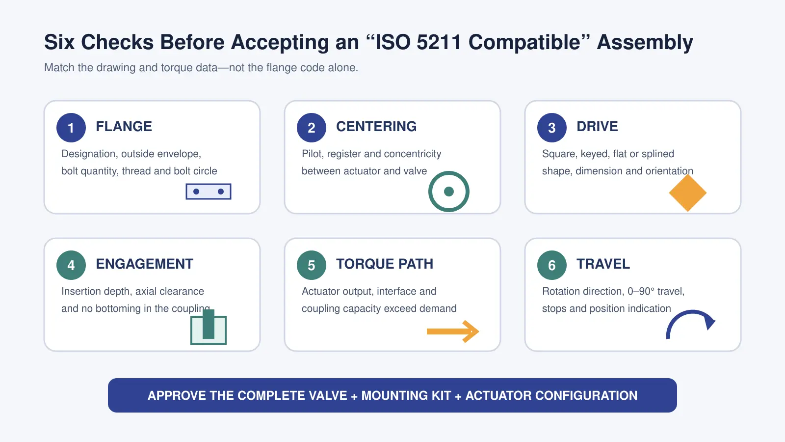
1. Flange Geometry and Fasteners
Confirm the flange designation on both drawings, then compare the bolt quantity, bolt-circle geometry, hole or thread details, fastener grade and available thread engagement. Verify that the actuator or bracket sits flat without interference from cast bosses, glands, insulation or piping.
2. Centering and Pilot Dimensions
Bolt clearance is not a precision alignment system. Where a pilot, spigot or register is used, its dimensions help locate the parts concentrically. If the mounting parts can shift significantly before the bolts are tightened, the installer must use an approved alignment method rather than relying on visual judgment.
3. Stem and Output-Drive Geometry
A valve stem may be square, keyed, double-D, flat-sided or splined. The actuator output or removable drive insert must match the shape, dimension and angular orientation. A coupling that “almost fits” can produce concentrated contact stress, backlash and permanent deformation.
4. Coupling Engagement
Check the effective engagement length in the assembled condition. The stem should not engage so shallowly that the contact area is inadequate, but it also must not bottom inside the actuator insert or coupling before the mounting faces are seated. Axial clearance and stem movement should follow the valve and actuator manufacturers’ instructions.
5. Torque Capacity
The actuator, flange interface, coupling, stem and mounting kit must all transmit the required torque. The weakest part controls the assembly capacity. Compare the design demand with the permitted values for every component rather than using actuator output torque as the only acceptance criterion.
6. Rotation and Travel
Confirm whether the valve closes clockwise or counterclockwise when viewed from the defined reference direction. Check the required travel angle, the location of the valve’s open and closed positions, and the relationship between mechanical stops, electrical limit switches and position indication.
ISO 5211 Is Not an Actuator Sizing Standard
A mounting flange does not determine the torque required to operate a valve. Valve torque changes with valve design, size, seat material, differential pressure, temperature, media, operating frequency and time in the closed position.
Obtain the valve manufacturer’s break torque, running torque and end torque for the specified service. Then compare those values with the actuator’s guaranteed output across the available supply range and operating direction. The selected safety factor should reflect uncertainty and service severity rather than being added mechanically to a generic valve-size table.
For a detailed method, use our valve actuator torque sizing guide. The mechanical interface and actuator sizing checks must pass independently.
Direct Mount or Bracket Mount?
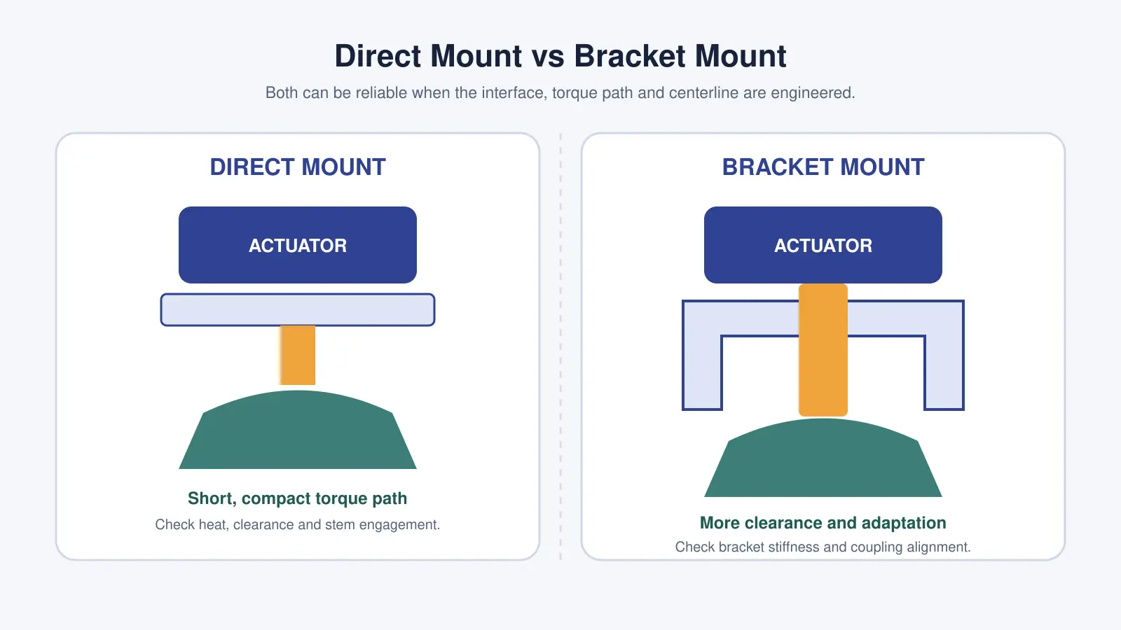
Direct-Mount Assembly
In a direct-mount arrangement, the actuator mounts on the valve’s integral platform, often using a drive insert or compact adapter. This can reduce overall height, part count and opportunities for bracket deflection. It is attractive for compact ball and butterfly valve packages.
Direct mounting is not automatically preferable. The actuator must have adequate clearance from the valve body, gland, piping and insulation. Process heat transferred through the stem and mounting platform must remain within the actuator’s permitted temperature. Maintenance access and manual override clearance also need review.
Bracket-and-Coupling Assembly
A bracket is used when the actuator cannot mount directly, when extra clearance is required, or when different interface sizes or stem geometries must be connected. The bracket and coupling are functional torque-transmission components—not cosmetic hardware.
Check bracket plate thickness, column or side-plate stiffness, weld quality where applicable, corrosion protection, fastener locking and dimensional tolerances. Under torque, an insufficiently rigid bracket can twist, tilt the actuator and introduce cyclic side loading into the stem and bearings.
ISO published ISO 5640:2024 for mounting kits used in part-turn valve actuator attachment. This is an important reference when the assembly includes an intermediate bracket or coupling.
Why Alignment Matters
The actuator output axis and valve stem axis should be concentric and free of angular error. Tightening bolts is not a valid method of pulling misaligned parts into position. Doing so can preload the stem, bearings, coupling or actuator output shaft before any operating torque is applied.
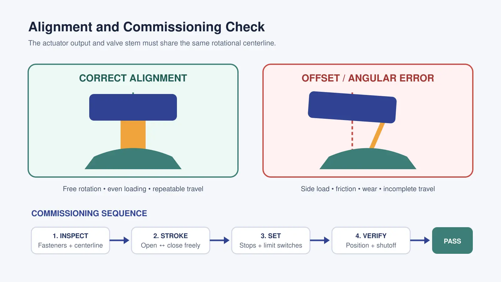
Potential symptoms of poor alignment include:
- Unexpectedly high motor current or air consumption
- Uneven or jerky travel
- Failure to reach the fully open or fully closed position
- Repeated coupling, stem, bearing or seal wear
- Loose mounting fasteners
- Position indication that disagrees with the actual valve position
- Reduced shutoff performance
For more detail on the failure mechanisms, see our article on the consequences of misaligned valve actuators.
Actuated Valve Mounting Review Checklist
| Review item | Information to approve | Typical evidence |
|---|---|---|
| Valve | Type, size, pressure class, stem geometry, rotation and service torque | Valve datasheet and dimensional drawing |
| Actuator | Motion, output torque, direction, duty, travel, drive and mounting flange | Actuator datasheet and output chart |
| Mounting kit | Bracket dimensions, coupling material, drive engagement and torque rating | Assembly drawing and material specification |
| Interface | ISO 5211 designation, bolt details, centering and allowable torque | Applicable standard and component drawings |
| Environment | Temperature, corrosion, washdown, hazardous area and installation orientation | Project datasheet and site classification |
| Controls | Power, control signal, feedback, fail action and local indication | Wiring diagram and control narrative |
| Testing | Full travel, stops, indication, torque behavior and shutoff | Inspection and functional test record |
Electrical requirements are covered separately in our guide to electric actuated valve control signals. Outdoor, washdown and hazardous-area requirements should also be checked using the electric actuated valve enclosure selection guide.
ISO 5211 compatibility confirms only part of the mechanical attachment. The actuator must still be selected by valve torque, duty, power source, fail action, controls and operating environment. See our complete valve actuator selection guide for the full package-selection process.
Commissioning the Complete Assembly
- Inspect before energizing. Confirm component tags, fastener tightness, coupling engagement, clearance and visual centerline alignment.
- Verify valve freedom of movement. Where the manufacturer permits manual operation, check that the valve can move through its intended travel without binding.
- Confirm rotation direction. Use controlled jogging or low-energy commissioning procedures to confirm that the command direction agrees with valve movement.
- Set mechanical stops correctly. Mechanical stops protect the valve and actuator; they should not be used to force the closure member beyond its designed position.
- Set limit switches and feedback. Adjust open and closed indication only after the mechanical positions are correct.
- Stroke the valve repeatedly. Observe smoothness, noise, current or air-pressure behavior and repeatability at both endpoints.
- Verify shutoff and process function. Perform the specified seat-leakage, functional or interlock tests for the project.
- Record the final settings. Keep the approved drawing, stop settings, switch settings and test results with the equipment documentation.
Procurement Information to Send the Supplier
To obtain a correctly matched complete actuated valve, provide:
- Valve type, size, pressure rating and connection
- Process medium, pressure and temperature
- Required valve materials and seat design
- Available valve torque data or complete operating conditions
- On-off or modulating service and operating frequency
- Electric supply or pneumatic supply range
- Control signal, position feedback and fail-position requirement
- Indoor, outdoor, washdown, corrosive or hazardous-area classification
- Space, orientation, insulation and maintenance constraints
- Required standards, certificates, inspection and test documentation
Vcore Valve supplies complete electric and pneumatic actuated valve assemblies rather than standalone actuators. We can review the valve torque, ISO 5211 interface, mounting kit, control requirements and environment as one package. Send us your application conditions and project datasheet for a configuration review.
Frequently Asked Questions
Does the same ISO 5211 flange code guarantee that an actuator fits a valve?
No. The same flange designation is an important starting point, but the bolt details, centering dimensions, drive shape, stem dimensions, coupling engagement, allowable interface torque, travel and clearances must also match.
Does ISO 5211 tell me what actuator torque to select?
No. ISO 5211 includes reference torque values for interfaces and couplings, but actuator sizing must start from the valve’s required operating torque under the specified service conditions, with an appropriate design margin.
Can an F10 actuator be mounted on an F07 valve?
Only with an engineered and rated mounting solution. An adapter bracket may connect different flange sizes, but its geometry, stiffness, fasteners, coupling and torque capacity must be verified for the complete assembly.
Is direct mounting always better than using a bracket?
No. Direct mounting is compact and reduces part count, while a bracket can provide necessary clearance, adaptation or thermal separation. Reliability depends on correct sizing, stiffness, engagement, alignment and installation.
What are the main signs of actuator-to-valve misalignment?
Typical signs include binding, jerky travel, high motor current, inconsistent endpoint indication, loose fasteners, coupling wear, stem or seal wear and failure to achieve full shutoff.
What should be tested before an actuated valve is shipped?
The assembled valve should be checked for component identity, mounting integrity, smooth full travel, correct rotation, open and closed positions, mechanical stops, limit switches, position feedback and the specified valve shutoff or leakage performance.
Technical References
- ISO 5211:2026 — Industrial valves — Part-turn actuator attachments
- ISO 5115:2023 — Industrial valves — Part-turn valve actuation
- ISO/TC 153 catalogue, including ISO 5640:2024 mounting kits for part-turn valve actuator attachment
- AUMA GS part-turn gearbox technical information and ISO 5211 valve attachment reference