Check Valve Selection for Seawater Desalination: Corrosion, Backflow and Pump Protection
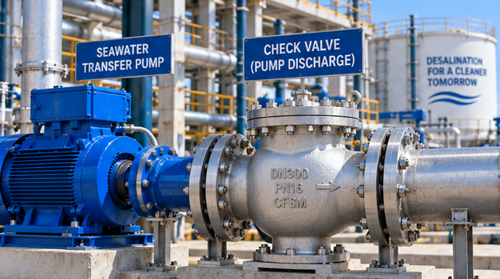
At a desalination plant, a non-return valve may be installed on a raw-seawater intake pump, a seawater transfer pump, a pretreatment backwash line or a treated-water booster system. These duties share a one-way-flow requirement, but they do not share identical hydraulic or corrosion conditions. Selecting a valve by nominal size and pressure class alone can leave a pump exposed to reverse rotation, valve slam or repeated disc chatter.
This guide focuses on the check-valve-specific decisions that a desalination EPC or procurement engineer must resolve. For the wider station arrangement and isolation-valve duties, use our Seawater Intake Pump Station Valves selection guide. For a component-by-component corrosion discussion, see Seawater Valve Corrosion: Body, Disc, Shaft and Seat Materials.
1. First Identify Which Water Stream the Check Valve Handles
| Service location | Main duty | Distinct selection concern |
|---|---|---|
| Open-seawater intake or transfer | Prevent reverse flow into stopped pumps | Marine organisms, sediment, chloride exposure, pump-trip transients |
| Pretreatment / filter backwash | Prevent unintended reverse flow between headers | Cycling, solids, fouling and maintenance access |
| RO feed / high-pressure section | Protect equipment against reverse flow | Project-specific high pressure, transients and approved valve design; do not substitute a low-pressure lined valve |
| Permeate / product-water booster | Prevent backflow to pump or storage | Water purity and downstream contamination controls |
| Brine / concentrate discharge | Control flow direction in concentrated saline stream | Higher salinity, chemistry, velocity and corrosion/erosion exposure |
Do not copy a material schedule from the raw-seawater header to the high-pressure RO or permeate system. Pressure class, water chemistry, cleanliness and corrosion allowances can differ substantially. The plant P&ID, hydraulic calculation and piping class govern each valve.
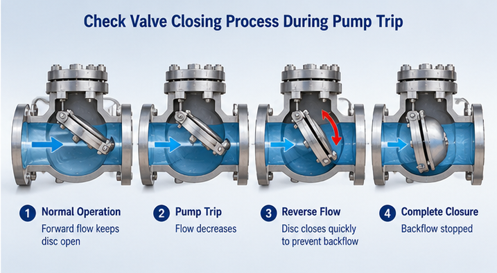
2. What Happens After a Seawater Pump Trips?
While the pump is running, forward flow holds the check-valve closure element open. After a power failure or trip, pump head decays; forward velocity falls and may reverse under downstream static head. The check valve should close before a damaging reverse velocity develops, but its actual behavior depends on the moving mass, spring force, hinge friction, valve position, flow profile and system transient.
A heavy swing disc that closes only after appreciable reverse flow may strike its seat with high impact. Conversely, selecting a “fast-closing” design solely by marketing label does not prove the complete pipeline is protected: pressure waves, column separation and surge can arise elsewhere in the system. The closing response must be checked against the system’s pump-trip transient analysis, not inferred from valve type alone.
Our general article on Check Valves for Pump Discharge covers baseline pump-discharge arrangements; this desalination guide adds saline-service material, debris and transient requirements.
3. Swing, Dual-Plate, Tilting-Disc or Axial: Compare the Closing Mechanism
| Design | Potential benefit | Project-specific concern |
|---|---|---|
| Swing check | Simple hinged disc; available in large flanged water-line configurations | Disc inertia, minimum flow velocity, hinge corrosion, installation direction and potential slam |
| Spring-assisted dual-plate | Compact face-to-face and spring-assisted closure | Plate flutter at low flow, pressure loss, spring/hinge materials and debris tolerance |
| Tilting-disc or damped check | Engineered closure behavior for selected large-pump systems | Dashpot configuration, orientation, maintenance, available envelope and actual transient performance |
| Axial / nozzle check | Short-stroke spring-assisted closing in suitable clean-flow duties | Raw-intake debris, required velocity, head loss and corrosion-resistant spring/guides |
A spring-assisted design may close earlier in a particular duty, but it is not universally the lowest-surge or lowest-loss choice. Obtain the manufacturer’s flow and closure data and compare alternatives at the minimum, normal and maximum operating points. A compact dual-plate check valve is one option to evaluate, subject to its confirmed seawater materials and hydraulic performance; it is not automatically interchangeable with a large lined swing check valve.
4. Size for Stable Opening, Not Only for Pipe Diameter
At normal duty, a check valve should open sufficiently and remain stable. Oversizing can leave a disc partly open, causing chatter, wear and additional pressure loss. Undersizing can raise velocity, erosion and pump energy consumption. The selection review should include:
- Minimum, normal and maximum flow rate for each pump and for parallel-pump operation.
- Available differential pressure, valve pressure-loss curve and pump head margin.
- Manufacturer’s minimum stable-opening flow or velocity, where applicable.
- Start/stop frequency and the possible operating duration at low flow.
- Discharge header static head, reverse-flow development and surge calculation.
- Allowable leakage, maintenance clearance and valve orientation.
5. Seawater Corrosion: Inspect Every Wetted Moving Part
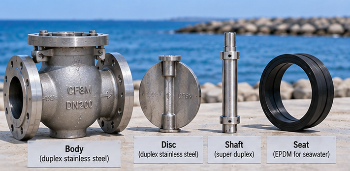
Rubber lining can isolate a ductile-iron or cast-steel body from seawater, but it does not protect an exposed hinge pin, spring, disc edge, fastener or damaged lining termination. Corrosion and deposits at the hinge can delay closing or prevent full seating, converting a materials problem into a pump-protection problem.
| Component | Possible construction direction | RFQ / inspection focus |
|---|---|---|
| Body and flow passage | Project-approved lined/coated iron or corrosion-resistant alloy | Lining continuity, flange edges, coating specification and holiday testing if specified |
| Disc / plates | Lined/coated substrate or approved seawater-resistant alloy | Exposed edges, crevices, impact wear and galvanic pairing |
| Hinge pin, shaft, spring | Corrosion-resistant material selected for actual chloride/temperature exposure | Pitting/crevice risk, accessibility, fatigue and material traceability |
| Seat / lining | EPDM or other verified elastomer for the actual medium | Water chemistry, temperature, compression, debris and abrasion |
| Bolting and external coating | Project-approved marine-environment system | Splash-zone exposure, galvanic compatibility and maintenance |
For example, a rubber-lined swing check valve can be considered for selected seawater pump-discharge lines, but the supplier must confirm its actual disc, hinge, seat and lining configuration for the project. A general “SS316” description is not proof that all internal parts will resist every seawater exposure, particularly stagnant crevices or higher-temperature chloride service. See our seawater component-material guide for a more detailed body/disc/shaft/seat review.
6. Debris, Biofouling and Intake-Water Solids
Raw seawater may contain sand, shell fragments, algae and marine growth despite upstream screening. These can obstruct a short-stroke valve, lodge on the seat or abrade a lining. Ask whether the valve is upstream or downstream of coarse screens, fine screens and filtration; define particle size, expected solids loading and flushing access. A clean-water axial check design should not be specified on a debris-prone intake solely because it is advertised as “non-slam.”
7. Installation: Orientation and Flow Profile Affect Closure
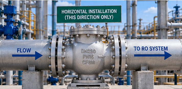
Confirm the manufacturer-approved horizontal or vertical orientation, vertical upward-flow limitations, hinge axis position and the minimum upstream/downstream straight lengths required by the design. A swing check that is suitable for horizontal installation is not necessarily suitable for vertical downward flow. Proximity to elbows, pump nozzles and reducers can create uneven flow and disc instability.
Before issuing a purchase order, compare the GA drawing with the actual pipe spool, supports and removal envelope. See the Check Valve Installation Guide for broader orientation and flow-direction considerations.
8. Pressure Class and Testing Are Not the Same as Surge Qualification
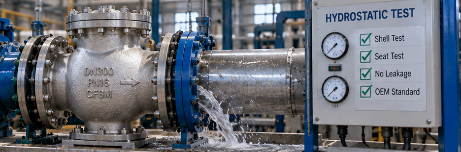
A valve marked PN16 or Class 150 may be suitable for a specified piping class, but the operating pressure, maximum/minimum transient pressure, temperature and body/lining limits must be evaluated separately. A shell or seat test verifies defined pressure-boundary or tightness requirements; it does not by itself demonstrate acceptable closure during a pump trip.
Agree on the applicable valve design/test standard, shell and seat test conditions, allowable reverse leakage, flow-performance data, lining inspection and any project-specific functional test. Our Valve Pressure Test Methods guide explains the difference between common test objectives.
9. Procurement Matrix: What to Ask the Manufacturer
| RFQ field | Required project information |
|---|---|
| Duty and location | Raw seawater intake, pretreatment, RO feed, brine or product water; P&ID tag |
| Hydraulic conditions | Minimum/normal/maximum flow, operating/design pressure and temperature, pump curve |
| Pump-trip data | Static head, number of pumps, trip scenario, transient results and allowable reverse velocity |
| Valve design | Swing, dual-plate, tilting-disc, axial or proposed alternative with supporting rationale |
| Installation | DN/NPS, flange drilling/facing, F/F, horizontal/vertical orientation, straight-run constraints |
| Materials | Body, disc, hinge/pin, spring, seat, lining, bolting and coating as separate line items |
| Water quality | Chloride/salinity, temperature, solids, biofouling, cleaning chemicals and stagnant periods |
| Performance | Pressure-loss curve, minimum stable-opening flow, closure characteristic and leakage criteria |
| Quality documents | GA, material certificates, coating/lining inspection, shell/seat test and approved ITP |
10. The Selection Decision
Choose the seawater check valve by following this sequence: service location → minimum/maximum flow → pump-trip transient → closure mechanism → pressure loss → complete wetted-material schedule → orientation → test and documentation plan. No single check-valve type is automatically suitable for every desalination pump station.
Explore the Rubber Lined Check Valve and Rubber Lined Swing Check Valve product concepts, or browse the rubber-lined valve category. For a project-specific technical review, send Vcore your P&ID, pump curve and valve datasheet.
Frequently Asked Questions
Which check valve is best for a seawater intake pump?
There is no universal choice. Compare swing, spring-assisted dual-plate, tilting-disc and axial designs using minimum flow, pump-trip transients, debris, pressure loss, installation and complete wetted-material requirements.
Does a non-slam check valve eliminate water hammer?
No. Check-valve closing behavior can reduce some slam risks, but the complete pump and piping system must be assessed for pressure waves, reverse flow and column separation.
Can a rubber-lined cast-iron check valve handle seawater?
It can be considered for selected seawater duties if the lining is suitable and every exposed disc, hinge, pin, seat and fastener is specified for the actual service. A lined body alone does not protect all wetted parts.
Can a check valve be installed vertically?
Only if the selected model and flow direction are approved for that orientation. Swing and spring-assisted designs have different installation constraints.
What data is needed to quote a desalination check valve?
Provide service location, size, pressure class, temperature, flow range, pump-trip and surge data, installation orientation, seawater chemistry and solids, complete materials, flange/F/F requirements and inspection documents.