Choosing a chemically compatible lining is only part of building a reliable valve connection. The installer must also protect the sealing faces and assemble the joint without imposing damaging loads. A connection that fits the bolt pattern can still have an unsuitable sealing contact area, gasket or pipe bore.
This guide covers the installation interface: what to inspect, what to confirm with the supplier and what to record before commissioning. It complements our valve gasket selection guide, which compares gasket families across a wider range of valve services.
1. Confirm the Supplied Valve Before Removing Protection
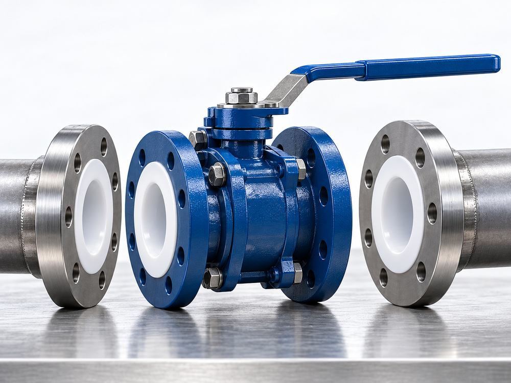
Match the valve tag and nameplate against the purchase order and approved drawing. Check the exact lining material: PTFE, PFA and FEP are distinct materials, even when a project informally calls all of them “PTFE lined.” Installation requirements must follow the supplied construction.
| Check | Information to confirm | Hold point |
|---|---|---|
| Service suitability | Chemical, concentration, temperature and pressure envelope | Resolve any mismatch before installation |
| Connection | Size, flange standard, facing, bolt pattern and face-to-face dimension | Do not assume matching nominal size means a compatible joint |
| Valve arrangement | Flow markings, actuator clearance and model-specific installation position | Use the approved drawing and IOM |
| Sealing faces | Cleanliness, scratches, distortion and handling damage | Refer questionable damage to the supplier |
| Assembly documents | Gasket decision, bolt specification and tightening procedure | Do not substitute an undocumented site practice |
Keep end protection in place until assembly is ready. Use lifting points approved for the valve package; do not insert lifting equipment through the lined bore. Clean exposed faces with a suitable soft cloth and approved cleaning method. Abrasive scraping or unapproved machining can change the sealing surface. CRP’s lined-piping manual explains the importance of protecting the liner flare during storage and handling.
2. Align the Flanges Before Applying Bolt Load
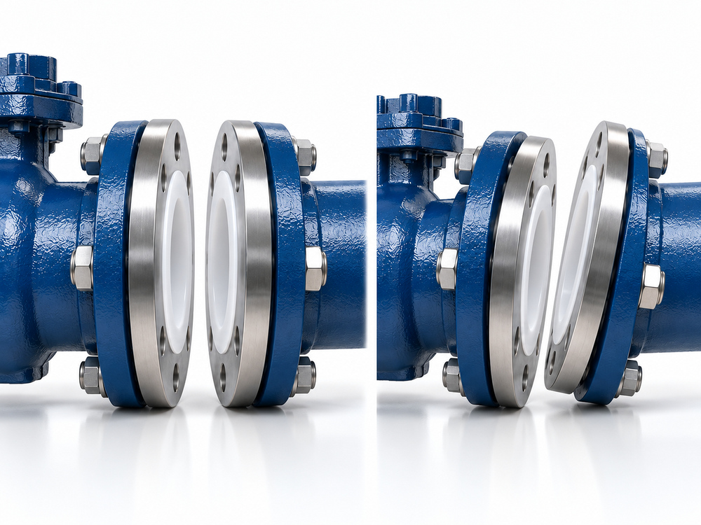
The mating flanges should be concentric and parallel, with the installation gap appropriate for the valve and approved gasket arrangement. CRANE’s XOMOX XLB instructions warn that misalignment and piping stress can damage the lining. Correct the pipe support or fit-up problem before tightening the joint.
For the installation record, treat alignment as three separate questions:
- Centre alignment: Does the pipe bore line up with the valve bore?
- Face parallelism: Is the gap consistent around the joint within the approved tolerance?
- Axial fit: Can the assembly be positioned without forcing the pipework against the valve?
Record the applicable tolerance from the project or equipment instructions. A visual statement such as “looks straight” is less useful than an identified inspection method and acceptance criterion. Bolts are joint fasteners, not a means of correcting pipe misalignment.
Additional checks for lined butterfly valves
For a PTFE lined butterfly valve, include the disc sweep and mating-pipe bore in the fit-up review. Ask the supplier to confirm clearance to thick-wall pipe, reducers and nearby components. The required disc position during insertion and subsequent travel checks is model-specific; do not assume instructions for a different seat construction apply.
3. Do PTFE Lined Valves Need Flange Gaskets?
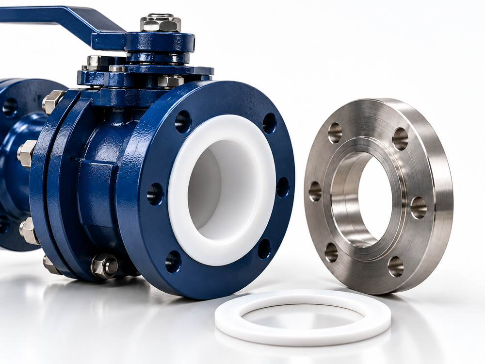
There is no universal yes-or-no answer. The liner may extend across the flange face and provide the sealing layer. Adding another gasket changes the joint thickness and loading behavior. Conversely, a transition to another flange material may require an approved gasket.
CRP describes normally assembling compatible lined-to-lined piping faces without an extra gasket, while recommending suitable gasket arrangements for certain dissimilar interfaces. The XOMOX XLB manual specifically calls for a PTFE-lined gasket when its valve mates with metallic or glass-lined pipe flanges. These examples show why the supplied model’s instructions must control the decision.
| Interface | Gasket decision | What to obtain |
|---|---|---|
| Compatible lined face to lined face | An additional gasket may be unnecessary | Written confirmation for both mating components |
| Lined valve to bare metal flange | A gasket may be required by the valve manufacturer | Approved material, dimensions, thickness and tightening basis |
| Lined valve to glass-lined or other dissimilar equipment | Requires interface-specific review | Acceptance from the valve and equipment suppliers |
| Integral sealing face on a lined butterfly valve | Follow the exact seat/liner design instructions | Permitted flange geometry and additional-gasket policy |
| Unidentified or damaged sealing face | Stop and resolve the condition | Inspection disposition rather than an improvised extra gasket |
Where a gasket is approved, record its inner and outer diameters as well as its material. It must match the intended contact area without intruding into the flow path. Do not select a spiral-wound, metallic or high-seating-load gasket merely because it is standard elsewhere in the plant. Its compatibility with the soft lined face needs explicit approval.
For a PTFE lined plug valve, request the flange sealing details with the GA drawing. Product-family names alone do not define the gasket arrangement.
4. Use a Joint-Specific Bolt Tightening Procedure
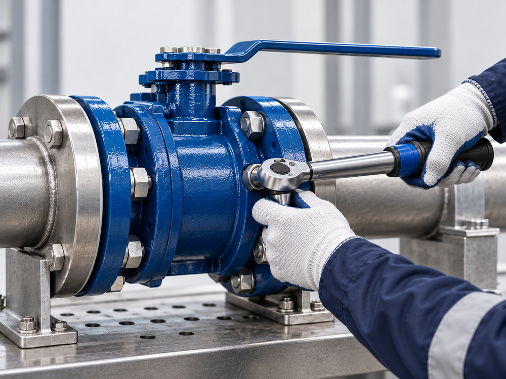
The aim is adequate, even sealing load without overloading the lined face. An approved bolt torque belongs to a defined assembly: valve size, flange arrangement, fasteners, washers where specified, gasket condition and thread lubrication. A value identified only as “DN100 torque” is incomplete.
CRP specifies torque-wrench tightening in diagonally opposed pairs for its lined joints. Obtain the pass sequence, final target and any settling recheck from the supplied valve instructions. Do not convert one manufacturer’s sequence into a universal procedure for all lined valves.
| Tightening record | Required entry |
|---|---|
| Joint identity | Valve tag, flange side and drawing reference |
| Bolting | Quantity, size, grade, coating, nuts and specified washers |
| Lubrication | Approved product and condition assumed by the torque instruction |
| Sealing arrangement | Lined-to-lined or exact approved gasket specification |
| Procedure | IOM/procedure revision, sequence, pass targets and final torque |
| Tool and execution | Wrench identification, calibration status, installer and date |
| Follow-up | Required recheck conditions and completion record |
Keep flange-bolt torque separate from body-joint torque, packing adjustment and actuator output. These values perform different functions and are not interchangeable. If paperwork uses the word “torque” without identifying the fastener or operating function, resolve that ambiguity before work begins.
Rechecking after settling or a thermal cycle
Some lined-valve instructions require a later tightening check to account for relaxation. Timing and conditions are product-specific. Agree on the check before commissioning so it is included in the work schedule. Do not infer permission to tighten a hot or pressurized chemical joint: use the approved isolation, cooling, depressurization and decontamination procedure.
5. Inspect the Completed Installation Before Chemical Service
Plan testing with the piping team and valve supplier. Confirm the permitted test medium, temperature, pressure, valve position and pressure direction, including any restrictions on a closed valve. A line pressure test and a valve seat-leakage test are different activities; one successful result does not establish all required performance.
Where the construction includes liner vent or telltale openings, preserve their intended function. Do not cover them with paint or treat them as unwanted leakage points to plug. Investigate any discharge through the approved maintenance process. Broader failure mechanisms are covered in our guide to valve failures in chemical pipelines.
| Observation | Review before returning to service |
|---|---|
| Flange seepage | Joint assembly record, face condition, alignment and gasket approval |
| Unexpected operating resistance | Disc/pipe clearance where applicable, assembly distortion and operator settings |
| Visible liner displacement or damage | Supplier inspection and disposition; do not conceal the defect |
| Leak recurs after startup | Thermal history, support loads and required follow-up checks |
Repeatedly increasing torque is not a troubleshooting plan. Document the symptom, make the system safe and identify the cause before reassembly. Preserve photographs and joint records so the supplier can assess the actual condition.
6. Request Installation Details with the Valve Order
A procurement package should connect the product specification to the site assembly requirements. For example, ordering a valve for an existing chemical skid should include information about the skid’s mating flanges, not only the valve’s nominal size and pressure class.
- Application: chemical composition, concentration, operating/design temperatures and pressures, including vacuum or cleaning conditions.
- Interface: flange standard, facing, material, bore, available space and adjacent equipment drawing.
- Sealing: written gasket requirement for each end, with dimensions and supply responsibility.
- Assembly: approved bolt specification, torque procedure, lubrication basis and inspection criteria.
- Handover: IOM, GA drawing, material/lining documentation, test records and commissioning restrictions.
For on-off chemical service, compare the installation envelope of the PTFE Lined Ball Valve with the plug and butterfly options linked above. Select the valve function first, then confirm that its actual flange and operator arrangement fits the project.
Frequently Asked Questions
Can PTFE lined valves be installed without a gasket?
Some approved lined-to-lined joints can. Other interfaces require a gasket. Obtain the requirement for the exact valve and mating component rather than assuming all lined faces seal in the same way.
Can I use the standard torque chart for a steel flange?
Only if it has been approved for the complete lined joint. Bolt strength alone does not define the acceptable load on the liner or gasket.
Can an extra gasket compensate for flange misalignment?
Do not use it as an improvised correction. Restore acceptable alignment and obtain approval for the sealing arrangement.
Should flange bolts be tightened again after startup?
Follow the supplied IOM and project procedure. If a follow-up check is required, document its timing and safe system condition before commissioning.
What if the joint leaks despite the specified torque?
Make the system safe and inspect the interface. Review alignment, sealing-face damage, gasket selection and the tightening record. Do not exceed the permitted torque without an approved engineering disposition.
Confirm Your Lined Valve Installation Requirements
Send Vcore Valve your chemical service conditions, valve size, mating flange details and piping drawing. We can review the proposed valve configuration and clarify the installation documents and interface information required for your project.
Technical References
- CRP — Lined Piping User Manual: handling, flare protection and lined-joint assembly principles.
- CRP — Let’s Talk Gaskets: gasket considerations at lined and dissimilar interfaces.
- CRANE — XOMOX XLB Lined Ball Valve IOM: an example of model-specific gasket, alignment and tightening requirements.
These references illustrate installation principles and differences between designs. They are not a Vcore torque schedule. The supplied valve’s approved instructions and project procedures govern installation.