A steam header can be fully pressurized while an isolated branch remains cold and at much lower pressure. Opening the main valve then creates two questions: can the valve and operator handle the opening load, and can the downstream system accept the incoming steam?
This guide focuses on the bypass decision and the information needed to purchase the complete arrangement. For the wider selection of closure designs, connections and materials, see our main steam isolation valve selection guide.
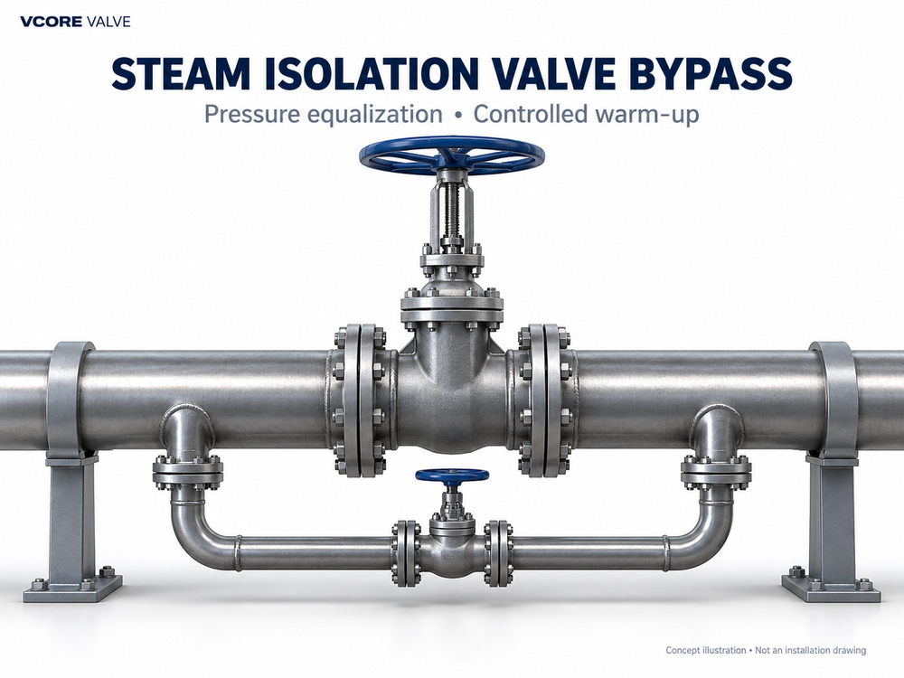
When Is a Steam Isolation Valve Bypass Needed?
The starting point is the main valve’s permitted opening differential pressure, not simply the line pressure or nominal valve size. Request the manufacturer’s operating limits for the actual temperature, closure design and selected operator.
| Operating situation | Reason to review a bypass | Evidence needed |
|---|---|---|
| Pressurized header with an isolated branch | Reduce differential pressure before main-valve opening | Maximum expected opening ΔP and approved operator capability |
| Large cold steam distribution section | Provide controllable initial steam admission | Warm-up analysis, drainage capacity and thermal limits |
| Repeated startup or standby changeover | Make startup conditions repeatable | Operating cases, instrumentation and sequencing requirements |
| Main valve qualified for the required ΔP; warm-up handled elsewhere | A separate local bypass may add little benefit | Approved system review and valve operating data |
| Valve remains difficult to move after line-pressure equalization | Investigate another mechanism | Checks for trapped cavity pressure, thermal binding or mechanical damage |
For parallel-slide gate valves, reducing pressure difference can reduce pressure-induced disc loading before opening. Velan specifically recommends a bypass for its pressure-seal parallel-slide design when very high differential pressure is present. This is a design-specific recommendation, not a universal pressure threshold for every gate valve.
For wedge gates, opening behavior also depends on wedge engagement, seat condition and temperature history. A larger handwheel or more powerful actuator is not a substitute for diagnosing an abnormal opening load. Our gate and globe valve stem thrust guide explains why pressure loading and required stem thrust must be evaluated separately.
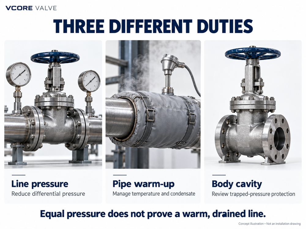
Pressure Equalization, Warm-Up and Cavity Relief Are Different Duties
Line-pressure equalization
A bypass admits steam to the isolated side so that the pressure difference across the main closure can decrease. If the downstream section continues consuming or discharging steam faster than the bypass supplies it, the required pressure balance may never develop. The downstream boundary conditions therefore belong in the bypass specification.
Controlled warm-up
Warm-up concerns the temperature response of the pipework and equipment. Steam contacting cold surfaces produces condensate, so drainage must be ready for startup duty. Spirax Sarco describes using a small control valve around an isolation valve where a larger valve provides insufficient warm-up control. Pressure equalization can be an additional benefit of this arrangement.
Matching pressure readings does not prove that the pipe wall is uniformly warm or that condensate has been removed. The plant must define separate temperature, drainage and pressure conditions for proceeding.
Valve-body cavity pressure management
The body cavity between seats can have a pressure different from either pipe connection. A line bypass connected only upstream and downstream may not communicate with that cavity. Review the sectional drawing and the manufacturer’s approved cavity-pressure provisions. Do not assume that an external line bypass prevents pressure locking, and do not add a drilled relief passage without design approval.
Pressure Equalization Example: What Changes Before Opening?
Consider the following invented pressure readings. They illustrate differential pressure only; they are not operating targets for a real steam system.
| Condition | Upstream pressure | Downstream pressure | Differential pressure |
|---|---|---|---|
| Before controlled admission | 40 barg | 2 barg | 38 bar |
| After downstream pressure rises | 40 barg | 37 barg | 3 bar |
The pressure difference has fallen substantially. Whether 3 bar is acceptable still depends on the approved valve limit and the plant’s startup criteria. There is no general “open below 3 bar” rule.
Use readings with the same pressure reference when calculating ΔP. Steam-flow sizing, however, requires appropriate thermodynamic properties and absolute pressures. These example readings do not establish bypass size, equalization time or valve opening torque.
How to Specify the Bypass Valve and Piping
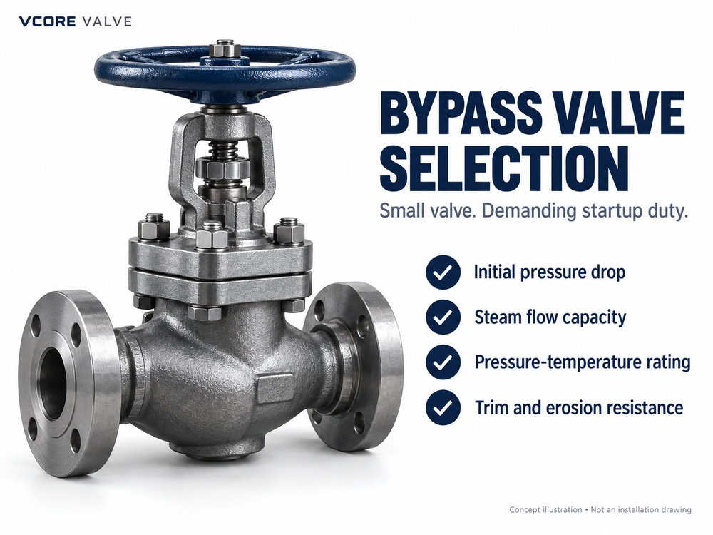
Select for the initial pressure drop
The bypass may experience its highest pressure drop when the downstream line is initially depressurized. Ask the supplier to check the required steam flow against that condition as well as the final approach to pressure balance. Depending on the pressure ratio and geometry, compressible flow can become choked; increasing pressure drop then does not produce a simple proportional increase in flow.
A smaller nominal size alone does not guarantee good control. Request a documented capacity calculation and a review of operating travel, noise, erosion and allowable pressure drop. A globe-style valve may suit controlled admission, but its trim and duty rating must be confirmed. A severe-duty startup condition may need an engineered control valve or staged pressure reduction.
Confirm pressure-temperature suitability
Review the complete branch: valve, fittings, tubing or pipe, connections, gaskets and bolting. The bypass is exposed to the steam system’s specified design envelope. Its small diameter does not justify a lower pressure-temperature rating.
For product options, review the Pressure Seal Globe Valve and Pressure Seal Gate Valve pages. These identify candidate product families; final suitability for the main or bypass duty requires application review. Our pressure-seal versus bolted-bonnet comparison covers the separate bonnet-construction decision.
Do not use a fixed bypass-to-main diameter ratio
The same main valve size can serve a short warm branch or a long cold header. Those systems need different startup flows. Provide downstream volume, pipe dimensions, initial temperature, insulation condition, connected equipment, permissible heating rate and the desired startup window. A competent sizing review should reconcile steam supply with heat absorption, condensation and downstream outflow.
Review Startup Logic and the Isolation Boundary Together
A bypass creates an additional path into the downstream system. Closing the main valve alone therefore does not establish isolation when that path remains open or leaks. Include the bypass in the plant’s isolation, lockout and verification arrangements.
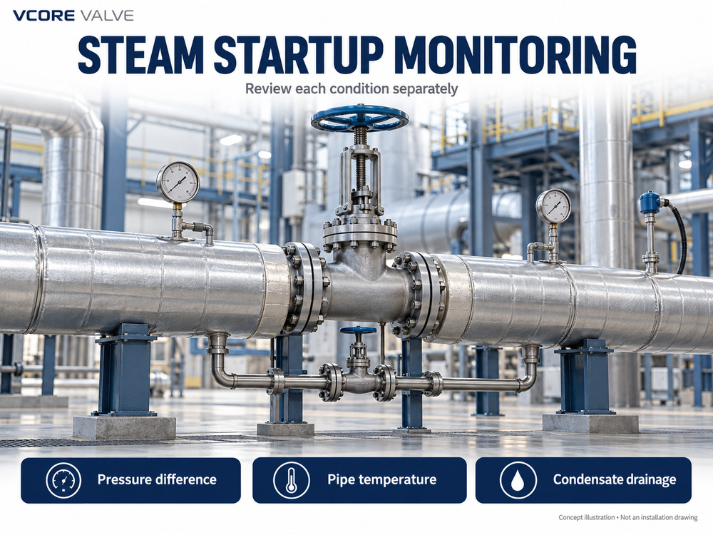
The following are engineering review stages, not a valve-operating procedure:
- Confirm the downstream boundary. Identify connected equipment, pressure ratings, maintenance status and any path to another steam source.
- Confirm readiness for steam admission. Review drainage, air removal, instrumentation, supports and the approved warm-up limits.
- Define the controlled admission stage. Establish what limits the initial steam flow and how abnormal pressure or temperature behavior is detected.
- Define main-valve opening permissives. Include the approved differential-pressure limit and independent thermal and drainage criteria.
- Define the normal-running and shutdown states. Record whether the bypass is to be closed, how its position is confirmed and how it participates in isolation.
Where the main valve provides protective or emergency isolation, engineering must assess whether the bypass could defeat that function. Its closure logic, actuation, position feedback and required leakage performance may need to be included in the protective system design.
Steam Isolation Valve Bypass RFQ Checklist
Request the main valve and bypass as a coordinated assembly or clearly identify the interface responsibilities between suppliers.
| RFQ item | Information to provide or request |
|---|---|
| Main valve | Size, closure design, pressure class, materials, ends, operator and permitted opening/closing ΔP |
| Steam conditions | Operating and design pressures and temperatures; saturated or superheated steam; startup extremes |
| Downstream system | Volume, initial condition, lowest equipment pressure rating, demand and possible reverse pressure |
| Bypass duty | Equalization, warm-up or both; frequency, flow range and startup-time objective |
| Layout | P&ID, connection points, drainage, supports, expansion allowances and operating access |
| Control and isolation | Manual or automatic duty, permissives, alarms, failure response and bypass isolation requirements |
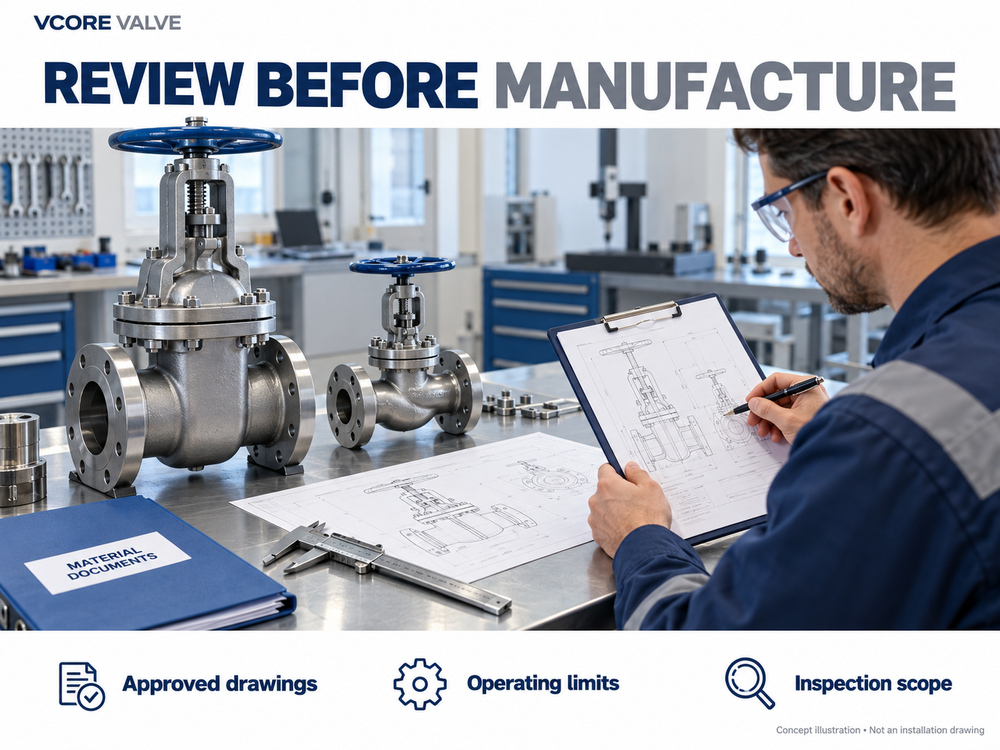
| Supplier evidence | Capacity calculation, approved GA drawing, flow direction, operating limits, material records and test scope |
| Acceptance | Applicable piping/valve standards, leakage criteria, inspection plan and site commissioning responsibilities |
Keep factory testing and site commissioning distinct. A pressure test establishes specified pressure-boundary or seat performance under its test conditions; it does not demonstrate the installed pipeline’s warm-up time or dynamic equalization behavior.
Frequently Asked Questions
Does every steam gate valve need a bypass?
No. The decision depends on permitted opening differential pressure, downstream warm-up needs and the existing system arrangement. Confirm it from the valve data and piping design rather than valve size alone.
Can I partially open the main gate valve to warm the pipe?
Do not assume a gate valve is suitable for sustained startup throttling. Obtain the manufacturer’s restrictions and follow the plant’s approved procedure. A dedicated admission valve can provide a better-defined control duty where required.
How long should pressure equalization take?
There is no universal time. Bypass capacity, downstream volume, condensation, leakage and connected loads all affect the result. Specify a startup objective and verify it through engineering analysis and commissioning.
Does the bypass eliminate pressure locking or thermal binding?
Not automatically. Line-pressure equalization may leave body-cavity pressure unchanged, and temperature-driven mechanical binding is a separate issue. The remedy must match the diagnosed mechanism.
Should the bypass remain open during normal operation?
Use the state defined by the approved system design. Startup-only bypasses are commonly returned to a closed state, but the required arrangement and verification must be documented for the project.
Specify the Main Valve and Bypass Together
Send Vcore Valve your steam conditions, main valve size, initial upstream and downstream pressures, opening requirements and P&ID. Include the warm-up duty and inspection scope so the main isolation valve and bypass configuration can be reviewed together.
Technical References
- Spirax Sarco — Steam Headers and Off-Takes: controlled warm-up and small bypass control-valve arrangements.
- Velan — Pressure Seal Parallel Slide Gate Valves: design-specific recommendation for equalization before opening at very high differential pressure.
This article supports industrial valve selection and RFQ preparation. Final sizing, pressure protection and operating procedures must follow the approved project design and the supplied equipment instructions.