Steam control valve oversizing occurs when the selected flow capacity is excessive for the actual operating envelope. It can leave low-load operation close to the seat, where useful regulating travel is limited and small movements may produce disproportionate flow changes. Confirm minimum, normal and maximum steam flow with the corresponding pressures and temperatures, then review required Cv/Kv, predicted travel, installed response and actuator performance. Hunting or low travel alone does not prove oversizing.
A steam control valve can pass the required peak flow and still perform poorly for most of its working life. The problem often appears during reduced production, warm standby or seasonal operation, when the process needs only a small fraction of the original design steam demand.
Operators may report temperature overshoot, unstable downstream pressure or a valve that repeatedly opens and closes near its seat. These observations deserve a capacity review, but they should not trigger an automatic valve replacement.
This article focuses on steam control valve oversizing: how to recognize the risk, what operating data to collect and how to compare corrective options. For the broader material, pressure-letdown and package-selection framework, see Steam Control Valve Selection for High-Pressure and High-Temperature Service.
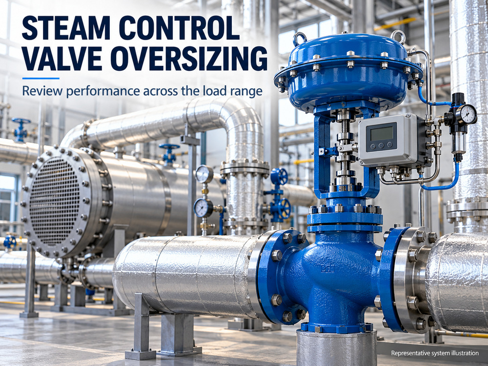
1. What Does Steam Control Valve Oversizing Mean?
Oversizing is a mismatch between available controllable capacity and the required duty. It is not determined by the nominal body size alone. Two valves with the same flange size can have different trim capacities and different flow characteristics.
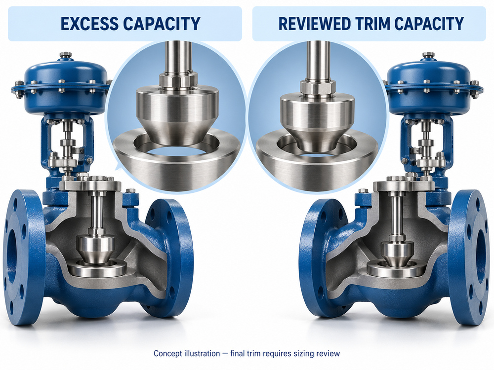
For a given steam condition, a higher-capacity trim may meet demand at less travel. If routine flow occurs in a narrow region near closure, the installed assembly may have difficulty making repeatable small flow adjustments. Manufacturer steam guidance identifies excessive capacity as a contributor to poor reduced-load control.[1]
| Term | Meaning for the review | Common misunderstanding |
|---|---|---|
| Pipe size | Selected for the piping system and its flow/velocity constraints. | The control valve must have the same nominal size. |
| Valve body size | Physical pressure-containing body and connection dimensions. | Every valve of that body size has identical capacity. |
| Rated Cv or Kv | Capacity of the specified valve/trim under defined reference conditions. | A higher coefficient is always a better selection. |
| Required Cv or Kv | Coefficient calculated for a particular operating case. | A single maximum-flow value proves good control at all loads. |
| Usable travel | Operating region supported by the trim and complete assembly. | One universal opening percentage applies to all designs. |
2. Why Oversizing Causes Problems at Low Steam Load
At low demand, a large-capacity valve has to reduce its opening to restrict steam flow. A small displacement may then represent a large change relative to the flow the process needs. The controller can struggle to hold pressure or temperature when that response is combined with process delay.[1]
Small Flow Demand Leaves Less Room for Positioning Error
Consider the difference between a small absolute flow disturbance during peak production and the same disturbance during standby. Its effect on the process can be much larger at low load. Ask whether the installed assembly can make the required adjustments repeatedly, rather than looking only at its full-stroke capability.
Near-Seat Operation Requires Model-Specific Review
Seat leakage, friction, feedback resolution and trim geometry matter when evaluating this region. Do not label all operation below 10% or 20% travel unacceptable. Obtain the manufacturer’s supported operating limits and assess the actual process response.
3. Common Reasons Steam Control Valves Become Oversized
The original selection may have been reasonable for a different operating envelope. Review how the design basis changed before deciding that the current valve was incorrectly manufactured or supplied.
| Source of excess capacity | What to investigate | Procurement improvement |
|---|---|---|
| Selection by line size | Was the trim chosen without a steam-flow calculation? | Request a calculation and predicted travel for every operating case. |
| Repeated safety margins | Were allowances added to heat load, mass flow and valve capacity independently? | Separate measured demand, design contingency and future expansion. |
| Startup dominates selection | Does a brief warm-up peak greatly exceed continuous demand? | Identify startup duration and steady-state requirements separately. |
| Lower production than planned | Have batches, connected equipment or operating hours changed? | Use current loads and identify any committed future duty. |
| Different trim installed | Does the installed trim match the approved rated Cv/Kv? | Verify model, trim code and maintenance/replacement records. |
| Changed pressure conditions | Do current inlet and outlet pressures differ from the sizing basis? | Recalculate with simultaneous pressures for each load case. |
4. Symptoms: Evidence of Oversizing or Another Problem?
Trend the command, actual travel, process variable and setpoint on the same time base. Add steam flow and pressures where reliable measurements are available. The diagnostic purpose is to establish whether an excessive capacity relationship is present, not merely to document movement.
| Observation | Why sizing may matter | Other causes to check |
|---|---|---|
| Low-load travel stays close to closure | Required flow may use little of the available capacity. | Feedback scaling, leakage and actual process demand. |
| Small travel changes produce large process changes | Installed response may be too sensitive in that region. | Sensor behavior, process delay and pressure disturbances. |
| Travel holds, then jumps | A large trim may amplify the resulting flow step. | Stiction, packing friction and actuator/air problems. |
| Good high-load control, poor low-load control | The minimum controllable duty may be the limiting case. | Condensate drainage, load-dependent dynamics and tuning. |
| Heating continues at a closed command | Minimum delivered steam may exceed demand. | Actual closure, seat leakage, a passing bypass or another heat source. |
Use Control Valve Hunting: Causes, Tests and Fixes for the detailed diagnostic workflow. This sizing review complements that guide; oscillation alone cannot identify the required repair.
5. Required Cv, Rated Cv and Installed Flow Characteristic
Calculate Each Operating Case
Request required Cv or Kv and predicted travel for minimum, normal and maximum duty. Confirm that calculations use the actual steam state, inlet pressure and outlet pressure for each case, with pressure references stated explicitly. A liquid sizing shortcut is not appropriate for steam.
The review should also consider the selected valve’s compressible-flow factors, any relevant piping corrections, choked-flow condition, noise and outlet velocity. A simple ratio of required Cv to rated Cv is not automatically a travel percentage. For the calculation framework, use How to Size a Control Valve: Cv, Kv and Travel.
Distinguish Inherent and Installed Characteristics
The inherent characteristic describes capacity versus travel under defined reference conditions. The installed response also reflects changes in system pressure losses. Equal-percentage trim is often considered for steam control, but its suitability still depends on the process and pressure conditions. It is not a substitute for correct capacity selection.[2]
6. Rangeability and Installed Turndown Are Not the Same
Published rangeability is associated with the valve’s defined controllable capacity range and stated conditions. Installed turndown describes the range over which the complete system can meet its control requirements. Changing pressures, seat leakage, mechanical response and process behavior can limit the latter.
Spirax Sarco’s control-theory guidance explains that oversizing can reduce the useful turndown available in service.[3] A catalogue ratio should therefore be treated as one input to the review, not as a guarantee that a particular heating process will control across the same ratio.
Illustrative Demand Example
A process requires 100 kg/h at minimum continuous load, 800 kg/h during normal production and 2,000 kg/h during a short startup period. The highest-to-lowest stated mass-flow ratio is 20:1. These figures are illustrative, not a completed Vcore project or a sizing result.
The ratio alone does not select a valve. The engineer still needs the simultaneous pressures, steam state, duration of each duty, acceptable process variation and trim/actuator data. No rated Cv, body size or travel percentage can be inferred from those three flows alone.
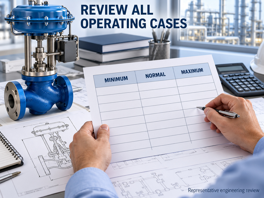
7. Minimum, Normal and Maximum Load: Build a Reviewable Datasheet
Ask the process owner to complete the operating inputs and the valve supplier to return the calculated outputs. Keep design pressure and design temperature separate from operating conditions used for flow sizing.
| Input or output | Minimum continuous load | Normal load | Maximum/startup load |
|---|---|---|---|
| Steam mass flow | ___ kg/h | ___ kg/h | ___ kg/h |
| Inlet pressure P1 | ___ bar(a) | ___ bar(a) | ___ bar(a) |
| Outlet pressure P2 | ___ bar(a) | ___ bar(a) | ___ bar(a) |
| Inlet temperature / steam state | ___ °C; state ___ | ___ °C; state ___ | ___ °C; state ___ |
| Duration / frequency | ___ | ___ | ___ |
| Required Cv/Kv — supplier output | ___ | ___ | ___ |
| Predicted travel — supplier output | ___ | ___ | ___ |
| Noise / outlet velocity review | ___ | ___ | ___ |
| Control and capacity acceptance | ___ | ___ | ___ |
If startup and maximum continuous operation differ, add another column. If the inlet pressure varies independently of demand, provide the relevant combinations rather than a single nominal supply value.
8. Corrective Options: Reduced Trim, Smaller Valve or Separate Duties
After confirming excess capacity, compare solutions against all required operating cases. The preferred option should resolve low-load performance without sacrificing peak capacity, shut-off duty or mechanical integrity.
| Option | When to evaluate it | Checks before approval |
|---|---|---|
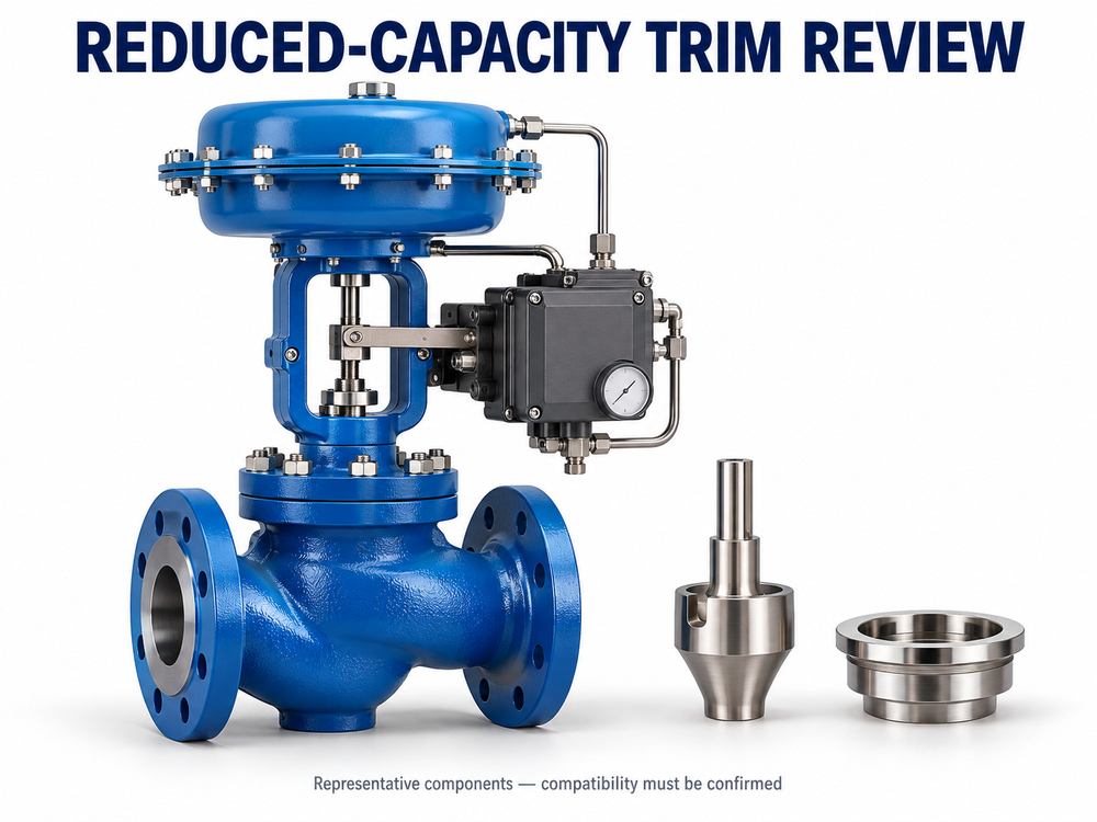
| Reduced-capacity trim in the existing body | The manufacturer offers an approved lower-capacity configuration. | New characteristic, operating travel, noise, actuator requirements and retained pressure/temperature limits. |
| Smaller valve with engineered connections | Body and trim reselection is appropriate for the actual duty. | Peak capacity, pressure losses, reducers, piping loads, outlet velocity, noise and installation dimensions. |
| Small and large valves serving different load ranges | One assembly cannot meet the required continuous and peak envelope. | Control sequence, crossover behavior, leakage, isolation, fail action and transition testing. |
| Separate startup and normal operating provisions | A short startup demand drives the capacity mismatch. | Approved operating philosophy, interlocks, protection, commissioning and operator procedures. |
| Retain the valve and correct a different fault | Capacity is suitable and another mechanism caused instability. | Evidence of corrected mechanical response, instrumentation or loop behavior. |
Why an Opening Limit Is Not Equivalent to Reduced Trim
Restricting maximum travel can cap available capacity, but it does not redesign the flow geometry at low opening. It can also remove needed peak flow. Treat any travel limitation as an engineered configuration change, with the manufacturer’s approval and a new capacity review.
Why Recalibration Alone May Not Resolve the Problem
Calibration checks the relationship between command and travel. It does not change the trim’s physical capacity. Correct feedback and actuator faults when found, using the Control Valve Positioner Calibration Guide, then reassess the process response.
9. Verify the Result at Low Load and During Load Changes
A successful repair or reselection should be demonstrated against agreed process criteria. Commissioning should include the lowest required continuous load, normal production and representative transitions, not only a full-open capacity check.
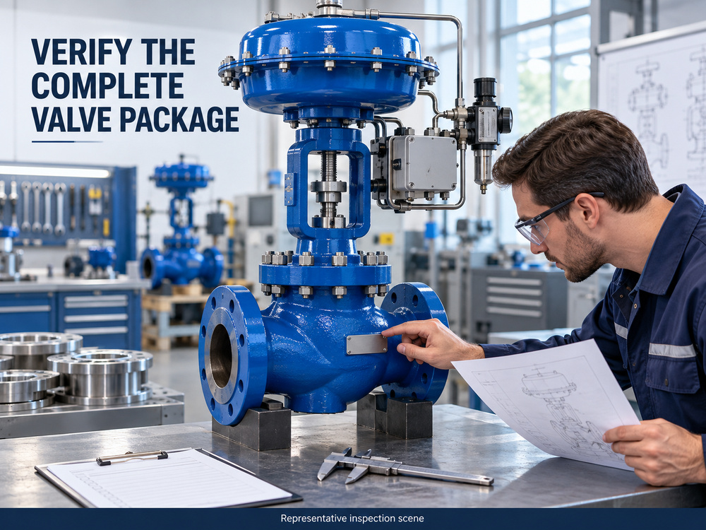
- Confirm configuration: Record the installed trim, rated capacity, actuator and positioner settings.
- Verify movement: Check actual travel and repeatability under the approved commissioning procedure.
- Record low-load behavior: Capture setpoint, process variable, command, travel and steam conditions.
- Review transitions: Observe load increases, load reductions and any crossover between valves.
- Confirm peak duty: Verify that the corrected configuration still meets the required maximum case.
- Close out: Record acceptance criteria, observations, remaining restrictions and approved final settings.
Do not assign a universal temperature tolerance or settling time. The process owner should define acceptable control performance. For heating equipment, assess condensate drainage and steam-side operating conditions as part of the system review rather than attributing every low-load disturbance to the control valve.
10. Procurement Checklist Before Requesting a Replacement
A replacement enquiry should describe the current problem and the operating evidence. “Same size, better control” does not give the supplier enough information to select a different capacity.
- Process duty: Pressure, flow or temperature control; equipment served; continuous versus batch operation.
- Operating cases: Minimum, normal, maximum and startup flow with corresponding P1, P2, temperature and steam condition.
- Existing valve: Manufacturer/model, body size, trim code, rated Cv/Kv, characteristic and travel.
- Observed problem: Load at which it occurs, synchronized trends and relevant maintenance history.
- Mechanical specification: Design pressure/temperature, materials, connection standard, face-to-face dimension and allowable piping loads.
- Control package: Actuator, supply conditions, signal, fail action, positioner and required response.
- Acceptance: Shut-off requirement, noise criterion, low-load stability and peak-capacity requirements.
- Supplier return: Case-by-case sizing, predicted travel, proposed trim, deviations, drawings and test/documentation scope.
Compare technical offers on the same operating-case basis. Ask suppliers to identify whether their proposal changes only trim, the complete valve, or the control arrangement.
11. Explore Vcore Valve’s Steam Control Valve Options
Product selection should follow the operating-case review. These product families provide starting points for a technical enquiry; the final body, trim and actuator must be confirmed for the stated steam duty.
Steam Control Valve
For project review of modulating steam pressure, flow and heating duties.
Key selection points:
Minimum-load controllability, rated and required Cv/Kv, predicted travel, steam conditions, noise and actuator sizing.
High Pressure Control Valve
For demanding pressure-letdown applications requiring detailed body and trim selection.
Key selection points:
Compressible-flow calculation, pressure drop, outlet conditions, trim construction and package performance.
Angle Control Valve
For selected applications where process conditions and piping layout support an angle-body solution.
Key selection points:
Body geometry, trim capacity, material selection, noise, outlet velocity and installation dimensions.
12. Final Selection Considerations
Steam control valve oversizing is fundamentally a capacity-and-control problem. A valve should satisfy peak demand while retaining suitable controllability at the lowest required continuous load.
Use actual operating cases, verified trim information and measured travel to establish the problem. Compare corrective options only after separating sizing from mechanical, instrument and process faults. Confirm the result through agreed low-load and transition checks.
For a wider project view, explore Power & Steam Valve Solutions and the Control Valve Selection Guide.
Frequently Asked Questions
1. What is steam control valve oversizing?
It is the selection of excessive flow capacity for the actual duty range, potentially leaving insufficient useful regulating travel at low load. Review trim capacity and installed conditions rather than body size alone.
2. Does low valve opening prove that the valve is oversized?
No. Verify actual travel, feedback calibration, load and pressure conditions. Compare the operating point with the selected trim data and its supported controllable region.
3. Should a steam control valve match the pipe size?
Not automatically. Select valve and trim capacity from the steam duty. A different valve size may be appropriate when the complete piping and operating review supports it.
4. Can PID tuning fix an oversized steam control valve?
Tuning may improve a suitable, mechanically healthy loop. It cannot change the physical capacity of the trim. A fundamental capacity mismatch requires engineering review.
5. Is equal-percentage trim always the solution?
No. It can be useful for steam applications, but capacity, installed pressure losses and process dynamics still require review. Its characteristic does not guarantee low-load control.
6. Can I fit reduced-capacity trim instead of replacing the valve?
Possibly, when the manufacturer provides an approved configuration. Recheck all operating cases, shut-off performance, actuator requirements and applicable limits.
7. What data is needed to review an oversized valve?
Provide operating-case flows, simultaneous pressures and temperatures, existing rated capacity and trim details, command/travel/process trends, actuator information and acceptance requirements.
Technical References
These references support general sizing and control principles. Product-specific operating limits and calculations must come from the approved valve data and project review.
- Spirax Sarco — Control Valve Sizing for Steam Systems: the relationship between capacity, lift and reduced-load control.
- Spirax Sarco — Control Valve Characteristics: inherent and installed flow characteristics.
- Spirax Sarco — Basic Control Theory: system turndown and control behavior.
Need to Review a Steam Control Valve Selection?
Share your operating conditions and existing valve information with Vcore Valve. A project review can identify the capacity, trim, actuation and documentation requirements for a technical offer.
For quotation or review, please provide:
Minimum, normal and maximum steam flow; inlet and outlet pressures for each case; steam temperature and condition; existing valve/trim details; control trends; connection requirements; actuator information; and any available datasheets or drawings.