Control valve hunting is repeated movement around the required operating point, but the valve is not always the root cause. Separate the controller command, actual valve travel and process-variable trend before changing PID settings. A steady command with irregular travel points toward stiction, deadband, air-supply restriction, linkage or positioner problems. A cycling command with accurate travel may point toward loop tuning, sensor delay, process interaction or excessive installed valve gain. Repair mechanical faults, tune the loop only after the final element responds correctly, and reselect the valve when sizing or trim architecture is fundamentally wrong.
Field Diagnostic Scenario
The process variable moves above and below setpoint. The controller output keeps changing. The actuator reverses direction every few seconds. Before anyone retunes the PID or replaces the valve, the team must determine which part of the loop is actually creating the cycle.
Diagnostic Snapshot: Read the Pattern Before Opening the Valve
Command Is Steady
Actual travel jumps or cycles.
Start with valve friction, stiction, linkage play, actuator pressure, positioner calibration and feedback accuracy.
Command Cycles
Actual travel follows accurately.
Review controller tuning, sensor delay, process dead time, interacting loops and excessive installed valve gain.
Command Changes
Travel responds late, then moves quickly.
Suspect stiction, deadband, packing friction, low air pressure, undersized tubing, restricted exhaust or weak positioner response.
Travel Looks Stable
Process variable still oscillates.
Investigate the process, sensor location, transmitter damping, upstream disturbances, heat-exchanger stall or interacting control loops.
First prove whether the command, actuator travel and process response are moving together.
What Control Valve Hunting Actually Means
Control valve hunting is repeated movement around an operating point rather than stable positioning. The cycle may be slow and regular, fast and noisy, or irregular with periods of no movement followed by sudden jumps.
The term is often used loosely. A moving valve does not prove that the valve caused the oscillation. The cycle can begin in the process controller, measurement system, valve-actuator assembly or process itself.
Frequent reversing movement can accelerate wear in packing, guides, linkages, actuator seals, positioner relays and trim. It can also create poor product quality, unstable pressure or temperature, excessive utility use and premature seat damage.
Three Signals to Trend Together
- Controller output or position command
- Actual valve travel or position feedback
- Process variable and setpoint
Without all three, the team may confuse a control-loop problem with a mechanical valve fault.
The Six-Step Diagnostic Ladder
Work from evidence to intervention. Each step should eliminate one layer of the control loop before the next adjustment is made.
STEP 01
Confirm That the Cycle Is Real
Check trend resolution, transmitter damping, sample rate, signal scaling and alarm filtering. A coarse or delayed trend can make a stable valve appear unstable—or hide rapid movement.
STEP 02
Compare Command with Actual Travel
If the command changes but travel does not move until the error becomes large, investigate deadband, stiction, packing friction, linkage backlash or insufficient actuator output. If actual travel follows the command closely, the valve may be responding correctly to a cycling controller.
STEP 03
Apply Small Bidirectional Step Tests
Where the operating procedure permits, apply small command changes in opening and closing directions. Record the command at which movement begins, travel delay, overshoot, settling time and any difference between opening and closing response.
STEP 04
Check Air, Actuator and Mechanical Movement
Measure pneumatic supply pressure while the valve is moving, not only at rest. Inspect the filter regulator, tubing, fittings, positioner output, actuator seals, stem alignment, coupling, travel stops, packing adjustment and mechanical guides.
STEP 05
Review Valve Sizing and Installed Gain
An oversized valve may pass normal flow close to the seat, where a small travel change produces a large flow change. Confirm required Cv or Kv, predicted travel and installed characteristic at minimum, normal and maximum conditions.
STEP 06
Tune the Process Loop Last
Only tune the controller after the valve assembly responds smoothly and repeatably. Tuning cannot remove mechanical backlash, stiction, air restriction, incorrect trim capacity or a process sensor installed in the wrong location.
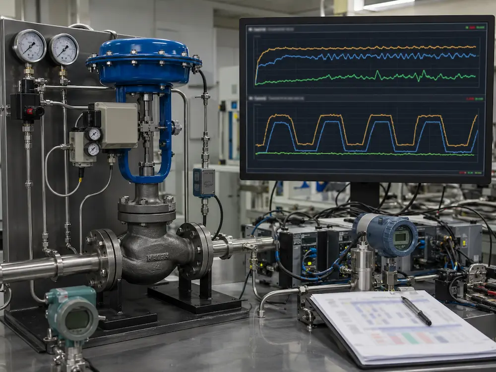
Trend Fingerprints: What Different Cycles Usually Suggest
Pattern A
Stick–Slip Movement
Trend: Command changes gradually, travel remains still, then jumps beyond the requested position.
Likely layer: Packing friction, stem deposits, guide wear, seat load, linkage stress or actuator force limitation.
First action: Compare opening and closing step response; inspect friction and mechanical alignment.
Pattern B
Positioner or Air-Supply Cycling
Trend: Travel oscillates rapidly around the command, sometimes with changing actuator pressure.
Likely layer: Positioner tuning, booster bypass, relay instability, restricted supply, water or oil contamination, actuator leakage.
First action: Trend supply and actuator pressure; inspect the air set and verify positioner configuration.
Pattern C
High Installed Valve Gain
Trend: Small travel changes cause large process-variable movement, especially near low opening.
Likely layer: Oversized valve, unsuitable characteristic, excessive pressure-drop allocation or low normal travel.
First action: Review sizing, travel and the installed flow characteristic.
Pattern D
Process or Controller Oscillation
Trend: Command cycles first and actual travel follows accurately.
Likely layer: Aggressive tuning, process dead time, interacting loops, transmitter delay, heat-exchanger stall or changing load.
First action: Review process dynamics and tuning after verifying the valve response.
Mechanical and Pneumatic Causes
Stem or Shaft Stiction
Stiction occurs when static friction prevents movement until actuator force exceeds the breakaway requirement. The valve may then move suddenly, overshoot and reverse direction.
Possible sources include excessive packing compression, damaged packing, corrosion, scale, crystallization, bent stems, guide wear, thermal distortion or side load from actuator misalignment.
Deadband and Backlash
Deadband is an input range through which the output does not respond as expected. Mechanical backlash in couplings, linkages, shafts or rotary drive trains can contribute to lost motion, especially when direction reverses.
Insufficient or Unstable Instrument Air
A static gauge reading does not prove adequate air during movement. Pressure can fall because of undersized tubing, blocked filters, restrictive regulators, solenoid-valve capacity, long tubing runs or shared supply demand.
Positioner and Booster Configuration
A positioner improves the relationship between command and actuator position, but incorrect tuning or an improperly adjusted volume-booster bypass can create rapid cycling. A better positioner cannot correct an oversized valve, damaged linkage or unsuitable trim.
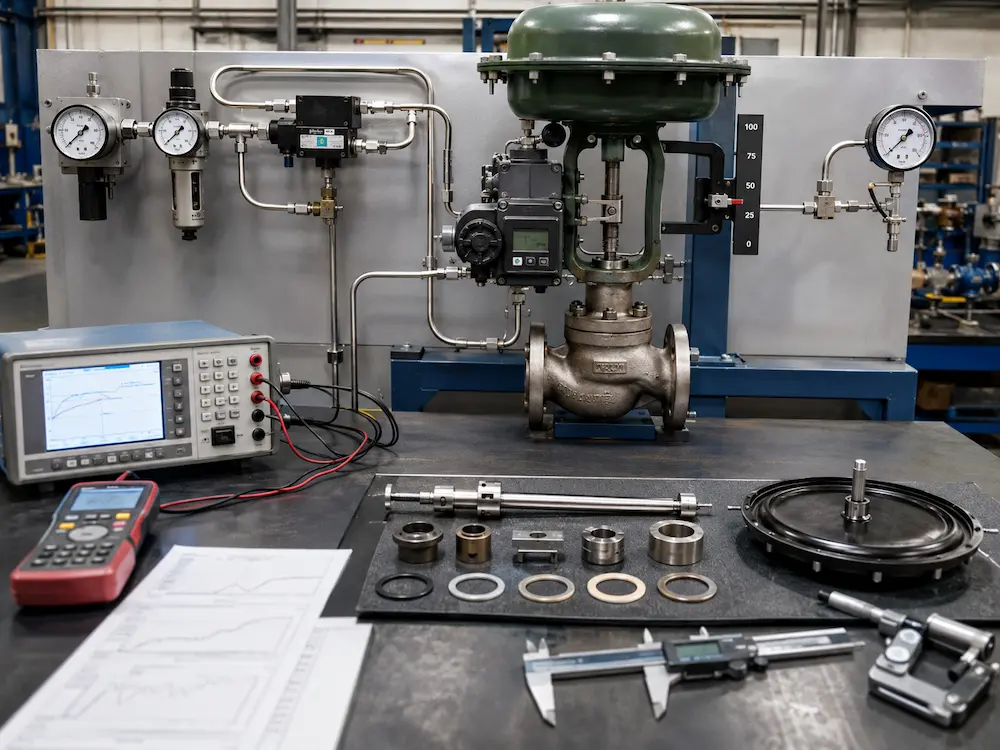
When the Valve Is Mechanically Healthy but Still Hard to Control
Oversized Valve
Normal flow occurs near the seat, leaving little usable travel and high process gain.
Review: Required Cv/Kv, normal travel, reduced trim or smaller body.
Wrong Flow Characteristic
The installed response becomes too aggressive or too flat as system pressure losses change.
Review: Linear vs equal-percentage and actual installed characteristic.
Severe-Service Instability
Cavitation, flashing, choked flow, high velocity or noise can produce vibration and unstable movement.
Review: Pressure drop, trim architecture, outlet conditions and materials.
Use How to Size a Control Valve for the capacity and travel review, and the Control Valve Selection Guide when body style, trim or actuator architecture must be reconsidered.
Repair, Tune or Reselect?
REPAIR
Use When the Valve Concept Is Correct
- Dirty air filter or restricted tubing
- Positioner calibration shift
- Loose coupling or moved travel stop
- Replaceable packing, seal or guide wear
- Minor actuator leakage
Proof required: Smooth bidirectional response after correction.
TUNE
Use After Mechanical Response Is Proven
- Valve follows command accurately
- Positioner response is stable
- Process cycle originates in controller dynamics
- Sensor and transmitter behavior are verified
- Interacting loops are understood
Proof required: Reduced process cycle without creating excessive valve movement.
RESELECT
Use When the Architecture Is Wrong
- Normal operation remains near the seat
- Maximum flow cannot be reached
- Wrong inherent or installed characteristic
- Recurring cavitation, erosion or plugging
- Actuator cannot meet force, speed or fail duty
Proof required: New sizing and package review using actual process cases.
Field Data to Record Before Requesting Support
Process
Setpoint, process variable, flow, P1, P2, temperature, medium and disturbance timing.
Control
Controller output, mode, PID settings, transmitter range, damping and sample interval.
Valve
Body type, size, trim, rated Cv/Kv, characteristic, actual travel and leakage requirement.
Actuator
Type, fail action, supply pressure, positioner model, actuator pressure and travel time.
A synchronized trend is more useful than a description such as “the valve is unstable.” Export command, actual position, process variable and setpoint over several complete cycles whenever possible.
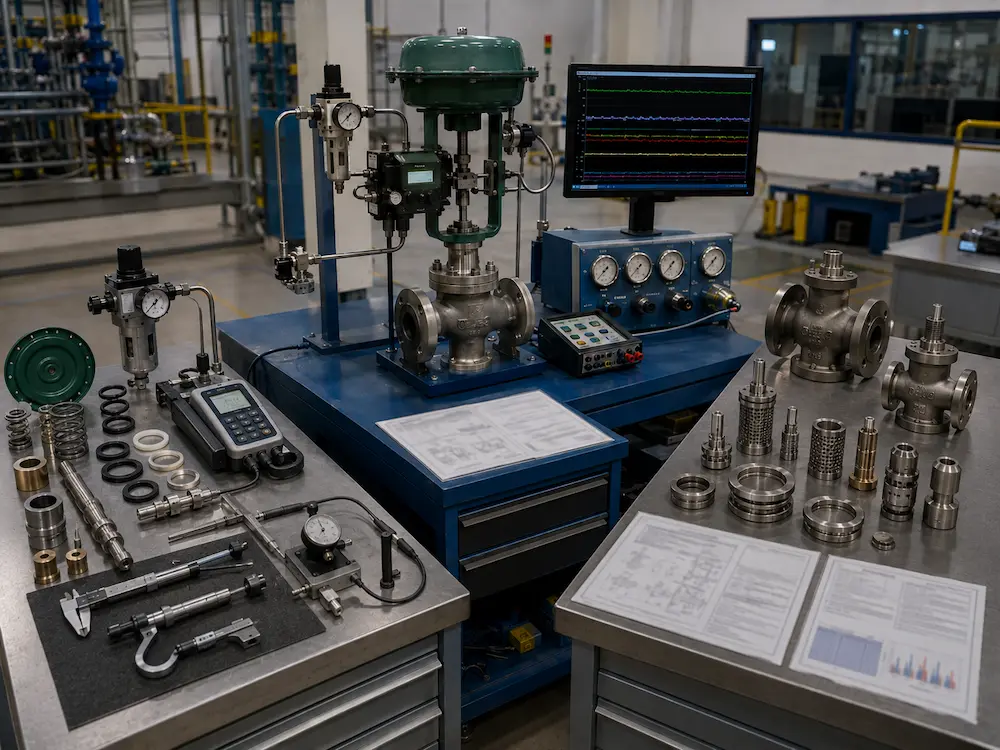
Send the Trend Before Replacing the Valve
Provide the process conditions, valve datasheet, actuator and positioner details, instrument-air pressure, command signal, actual travel and process-variable trend. Vcore Valve can help separate a repair problem from a tuning problem or an incorrect valve selection.
Related Technical Resources
Technical References
Frequently Asked Questions
What causes a control valve to hunt?
Possible causes include aggressive controller tuning, process dead time, valve stiction, deadband, linkage backlash, unstable instrument air, incorrect positioner settings, oversizing, excessive installed gain and interacting process loops.
How can I tell whether the valve or controller is causing the oscillation?
Trend controller output, actual valve travel and the process variable together. A steady command with irregular travel points toward the valve or actuator. A cycling command with accurate valve travel points more strongly toward controller or process dynamics.
Can PID tuning fix valve stiction?
No. Tuning may change the appearance of the cycle, but it does not remove packing friction, mechanical binding, backlash, low actuator force or air-supply restriction. Correct the mechanical response before tuning the loop.
Why does an oversized control valve cause hunting?
An oversized valve may operate close to the seat, where a small change in travel produces a large change in flow. This high installed gain can make stable control difficult and leave insufficient usable travel at normal load.
When should a hunting control valve be replaced?
Replacement or reselection is appropriate when the valve is fundamentally oversized, undersized, uses the wrong flow characteristic, repeatedly suffers severe-service damage, or cannot meet the required actuator and control duty after repair.