A pressure regulator is usually a self-contained pressure-control device that uses process pressure and an internal spring, diaphragm, piston or pilot system to maintain upstream or downstream pressure without a separate controller. A control valve is normally the final control element in an external loop using a transmitter, controller, actuator and often a positioner. Choose a regulator for a defined local pressure-control duty when simplicity and independence from external utilities matter. Choose a control valve when the process requires remote setpoint changes, multiple control variables, wider automation integration, diagnostics, engineered fail action or coordinated plant control.
A pressure regulator and a control valve can both throttle fluid and change pressure. From the outside, they may even appear to perform the same job. This causes a common procurement question:
Should the project use a pressure regulator or a control valve?
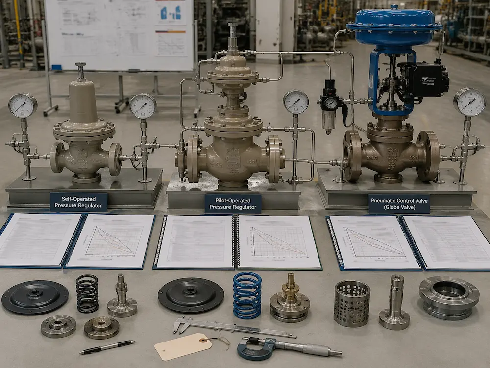
The correct answer depends less on the valve body and more on the control architecture. A regulator usually senses pressure mechanically or through a pilot and adjusts itself without a separate controller. A control valve receives a command from an external control system and can respond to pressure, flow, temperature, level or another measured variable.
This guide compares control valve vs pressure regulator by operating principle, accuracy, load response, utilities, automation, fail action, maintenance and application risk.
The Difference in One Table
| Comparison Item | Pressure Regulator | Control Valve |
|---|---|---|
| Primary function | Maintains a defined upstream or downstream pressure. | Modulates flow to control pressure, flow, temperature, level or another process variable. |
| Control signal | Usually senses process pressure directly through a diaphragm, piston, bellows or pilot. | Receives an external pneumatic, analog, digital or communication command. |
| External power | Direct- and pilot-operated regulators commonly work without separate electrical or instrument-air power. | Normally requires instrument air, electricity, hydraulic power or another actuator utility. |
| Setpoint adjustment | Often local mechanical adjustment; remote loading is possible on selected designs. | Can be changed remotely through PLC, DCS, controller or supervisory logic. |
| Control scope | Usually dedicated to one pressure-control function. | Can participate in cascade, ratio, override, split-range and multi-variable control strategies. |
| Typical complexity | Compact and self-contained. | Includes valve, actuator, positioner, transmitter, controller and accessories. |
| Main performance concerns | Droop, lockup, supply-pressure effect, creep, pilot stability and flow-curve limits. | Sizing, installed gain, deadband, actuator force, tuning, cavitation, noise and signal integrity. |
How a Pressure Regulator Works
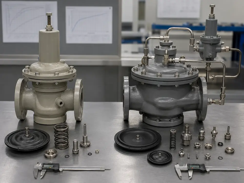
A pressure regulator balances forces to move an internal valve element. Depending on the design, a spring or loading pressure acts against the pressure sensed by a diaphragm, piston or bellows.
The regulator opens or closes automatically as demand and pressure change. It does not normally wait for a separate controller to calculate an output signal.
Pressure-Reducing Regulator
A pressure-reducing regulator controls downstream pressure. When downstream demand increases and pressure begins to fall, the regulator opens further. When downstream demand decreases and pressure rises, the regulator moves toward the closed position.
Typical uses include:
- Natural-gas distribution
- Instrument-gas systems
- Steam pressure reduction
- Water and utility pressure control
- Gas-cylinder and analyzer systems
- Equipment inlet-pressure control
Back-Pressure Regulator
A back-pressure regulator controls pressure upstream of the regulator. It opens when upstream pressure rises above the set condition and throttles to maintain the required upstream pressure.
This is different from a pressure relief valve. A back-pressure regulator is a process-control device intended for continuous or modulating pressure control. A relief or safety valve is a protective device selected to discharge excess pressure under defined overpressure conditions.
For overpressure-protection fundamentals, review the Pressure Relief Valves Guide.
Direct-Operated Regulator
A direct-operated regulator connects the sensing element directly to the internal valve mechanism. It is comparatively simple, compact and economical.
Its suitability depends on the acceptable pressure variation across the required flow range. Large changes in demand can produce a wider proportional response or droop than the process allows.
Pilot-Operated Regulator
A pilot-operated regulator uses a smaller pilot system to control the main valve. The pilot senses pressure and uses process fluid or loading pressure to position the main valve.
Pilot-operated designs may provide higher capacity, narrower proportional band or better pressure control across changing demand than a basic direct-operated regulator. They are still normally considered self-operated when process pressure supplies the operating energy and no separate plant utility is required.
How a Control Valve Works
A control valve is normally one part of a complete feedback or command system.
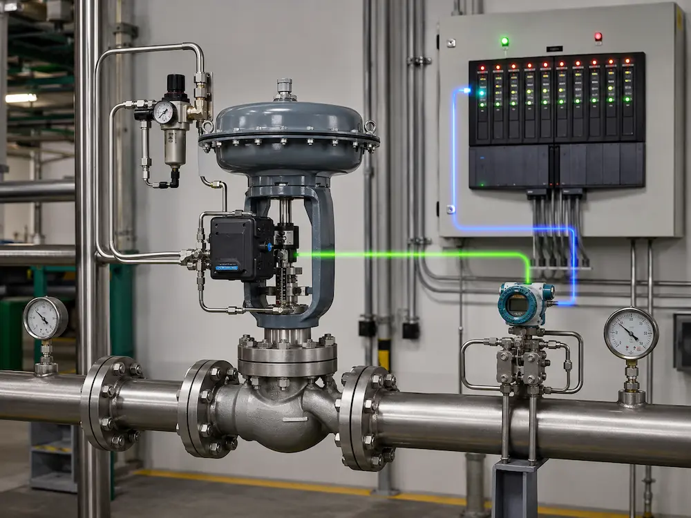
A typical pressure-control loop includes:
- A pressure transmitter measures the process pressure.
- A controller compares the measurement with the required setpoint.
- The controller sends a command to the valve positioner or actuator.
- The actuator moves the valve trim.
- The changed flow modifies the process pressure.
The controlled variable does not need to be pressure. The same valve package can be selected for flow, temperature, level, composition or another process requirement when the correct sensor and control logic are used.
A complete control valve package may include:
- Globe, angle, rotary, butterfly or eccentric plug valve body
- Pneumatic, electric or hydraulic actuator
- Digital or electro-pneumatic positioner
- Air filter regulator
- Solenoid valve
- Limit switches or position transmitter
- Volume booster or speed-control accessories
- PLC, DCS or standalone controller interface
For the full valve-body and trim decision path, use the Control Valve Selection Guide.
Why a Regulator Pressure Is Not Perfectly Constant
A regulator setpoint should not be interpreted as one perfectly fixed outlet pressure under every flow and inlet condition.
Droop
Droop is the change in controlled pressure as flow changes. In a pressure-reducing regulator, downstream pressure commonly decreases as flow demand increases.
Regulator selection should therefore use the manufacturer’s flow curve at the expected inlet pressure, outlet pressure, medium and flow range. The useful operating region is more important than one catalogue set-pressure value.
Lockup
Lockup is the pressure increase required for the regulator to move from a flowing condition to a fully closed condition. The no-flow pressure may therefore be higher than the pressure observed while fluid is flowing.
Supply-Pressure Effect
Supply-pressure effect describes how a change in inlet pressure affects controlled outlet pressure. The direction and magnitude depend on the regulator design.
Balanced valve elements, pilot systems or multi-stage arrangements can reduce the effect, but the buyer should still confirm the manufacturer’s published performance.
Creep
Creep is a gradual increase in downstream pressure after the regulator should have closed. It can indicate contamination, seat damage, improper assembly or another sealing problem.
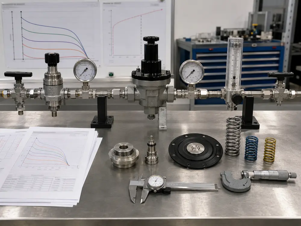
Do not approve a pressure regulator from inlet pressure, outlet setpoint and connection size alone. Review its flow curve, droop, lockup, inlet-pressure variation, medium properties and required maximum flow.
When a Pressure Regulator Is Usually the Better Choice
A pressure regulator may be the more practical choice when the following conditions apply.
The Duty Is Local and Pressure-Based
The device only needs to maintain upstream or downstream pressure at one location. The process does not require temperature, flow, level or coordinated multi-variable control.
External Utilities Are Unavailable or Undesirable
A self-operated regulator can continue to function without instrument air, electrical power, controller output or communication infrastructure.
Simplicity Is More Important Than Advanced Automation
A regulator can reduce the number of instruments, cables, tubing runs, control panels and software functions required for a simple pressure-control station.
The Required Flow and Pressure Range Fits the Regulator Curve
The selected regulator must keep pressure within the allowable band throughout the expected inlet-pressure and flow range. It should not be selected only for the normal operating point.
Fast Local Mechanical Response Is Beneficial
Because the regulator senses pressure locally, it can respond without waiting for a remote transmitter, controller calculation and command path. Actual dynamic performance still depends on regulator sizing, sensing arrangement, volume and system stability.
When a Control Valve Is Usually the Better Choice
The Setpoint Must Change Remotely
A control valve can receive changing setpoints from a DCS, PLC or supervisory system. This is useful for batch processes, load-following systems, recipe changes and plant-wide optimization.
The Controlled Variable Is Not Only Pressure
A control valve can regulate:
- Flow
- Temperature
- Level
- Differential pressure
- Mixing ratio
- Steam condition
- Multiple coordinated process variables
The Process Requires Advanced Control Logic
Control valves can participate in:
- Cascade control
- Ratio control
- Split-range control
- Override control
- Feedforward control
- Remote shutdown or interlock logic
Diagnostics and Position Feedback Are Required
A digital positioner can report travel, command deviation, air-supply condition, friction indicators and other diagnostic information depending on the selected device and communication system.
Fail Action Must Be Engineered Independently
A control valve package can be designed to fail open, fail closed or fail in place through spring action, stored energy, lock-up systems or project-specific control architecture.
The Valve Must Manage Severe Pressure-Drop Conditions
A control valve can be supplied with reduced trim, low-noise cages, anti-cavitation trim, multi-stage pressure reduction, hardened components or specialized body styles.
When cavitation, flashing or high aerodynamic noise is possible, review Control Valve Trim Options for Cavitation and Noise Reduction.
Decision Matrix by Project Requirement
| Project Requirement | Likely Starting Point | Engineering Check |
|---|---|---|
| Simple local downstream pressure reduction | Pressure-reducing regulator | Flow curve, droop, lockup, inlet variation and seat compatibility. |
| Maintain upstream pressure in a process or return line | Back-pressure regulator | Accumulation, flow range, discharge destination and distinction from relief duty. |
| Steam distribution pressure with no instrument air | Direct- or pilot-operated steam regulator | Steam quality, strainer, separator, condensate arrangement, load variation and pressure band. |
| Remote pressure setpoint from DCS | Control valve | Transmitter range, tuning, actuator, positioner, fail action and communication. |
| Pressure control coordinated with flow or temperature | Control valve | Control strategy, interaction between loops and valve installed gain. |
| Very wide load range and demanding pressure stability | Pilot regulator or control valve after comparison | Required control band, flow turndown, inlet variation, utilities and lifecycle support. |
| Safety overpressure protection | Safety or relief valve | Applicable code, set pressure, relieving capacity and discharge system. Do not substitute a regulator or normal control valve. |
Control Accuracy: Avoid One Universal Claim
It is not technically correct to state that every control valve is more accurate than every regulator.
A pilot-operated regulator can provide tight and repeatable pressure control in a properly selected duty. A poorly sized control valve with excessive deadband, incorrect tuning or an unsuitable transmitter can perform worse.
The comparison should use actual project criteria:
- Allowable pressure variation
- Minimum, normal and maximum flow
- Minimum and maximum inlet pressure
- Required response time
- Setpoint-change frequency
- Process-volume and piping dynamics
- Measurement accuracy
- Required turndown
- Utility and maintenance availability
A regulator is evaluated largely through its published pressure-flow performance and operating limits. A control valve is evaluated through valve sizing, predicted travel, installed characteristic, actuator response, measurement quality and loop tuning.
For Cv, Kv and predicted-travel requirements, read How to Size a Control Valve.
Failure Modes and Safety Behavior
Regulator Failure Considerations
Possible regulator problems include:
- Seat contamination and downstream pressure creep
- Diaphragm, bellows or pilot damage
- Blocked sensing line
- Incorrect spring range
- Instability caused by oversizing or poor piping arrangement
- Freezing, condensation or Joule-Thomson cooling in gas service
- Droop or supply-pressure effect outside the allowable process band
The result of a diaphragm or pilot failure depends on the regulator design. Buyers should request the documented failure behavior rather than assuming the regulator will always fail closed.
Control Valve Failure Considerations
Possible control-valve problems include:
- Loss of instrument air or electrical power
- Positioner or signal failure
- Actuator undersizing
- Incorrect fail-action accessories
- Stem or shaft friction
- Trim erosion, cavitation or plugging
- Loss of transmitter signal or controller output
The complete fail-open, fail-close or fail-in-place response must be tested as an assembled package.
For actuator selection, use the Valve Actuator Selection Guide.
Maintenance and Lifecycle Comparison
| Maintenance Area | Pressure Regulator | Control Valve |
|---|---|---|
| Primary mechanical parts | Seat, plug or poppet, spring, diaphragm, piston, bellows and pilot parts. | Body, trim, stem or shaft, packing, actuator, mounting and accessories. |
| Calibration | Set-pressure and performance checks; pilot adjustment where applicable. | Positioner zero/span, travel, feedback, controller loop and fail-action testing. |
| Diagnostic capability | Usually limited unless separate instrumentation is installed. | Can include digital valve diagnostics and remote position feedback. |
| Support requirement | Regulator repair kits, springs, diaphragms, pilots and flow-performance data. | Trim parts, packing, actuator seals, positioner support, calibration tools and control-system knowledge. |
Information Required Before Quotation
For a Pressure Regulator
- Pressure-reducing or back-pressure duty
- Medium and chemical composition
- Minimum and maximum inlet pressure
- Required controlled pressure and allowable variation
- Minimum, normal and maximum flow
- Operating and design temperature
- Connection size and standard
- Body, trim, diaphragm and seat material requirements
- Direct-operated, pilot-operated or remote-loaded preference
- Expected no-flow condition and lockup requirement
- Noise, freezing, condensation or contamination risk
- Required pressure gauges, strainer, relief protection and documentation
For a Control Valve
- Controlled variable and control philosophy
- Minimum, normal and maximum process cases
- Inlet and outlet pressure for every case
- Fluid properties and temperature
- Required Cv or Kv and predicted travel
- Valve body and trim preference if specified
- Leakage standard and class
- Actuator type and minimum utility supply
- Fail-open, fail-close or fail-in-place requirement
- Control signal, feedback and communication protocol
- Hazardous-area, enclosure and ambient conditions
- Inspection, calibration and documentation requirements
Procurement Decision Checklist
- Define the variable: Is the device controlling only local pressure, or another process variable?
- Define the architecture: Should it be self-operated or controlled by PLC/DCS?
- Define the operating range: What are minimum, normal and maximum flow and inlet pressure?
- Define the pressure band: How much pressure variation is acceptable across changing demand?
- Check utilities: Are instrument air, electricity and control signals available?
- Check setpoint requirements: Is local adjustment enough, or must operators change it remotely?
- Check failure behavior: What should happen after loss of signal, power, diaphragm or pilot function?
- Check severe service: Are noise, cavitation, flashing, erosion, freezing or dirty media possible?
- Check maintenance: Are repair kits, calibration tools, technicians and spare parts available?
- Keep safety independent: Confirm whether separate relief or safety protection is required.
Send the Pressure-Control Duty Before Choosing the Device
Provide the medium, inlet-pressure range, required controlled pressure, flow range, temperature, control philosophy, available utilities, fail requirement and documentation scope. Vcore Valve can review whether the project should use a self-operated regulator, pilot-operated regulator or actuated control valve package.
Related Technical Resources
- Control Valve Selection Guide
- How to Size a Control Valve
- Equal Percentage vs Linear Control Valve
- Control Valve Leakage Classes
- Valve Actuator Selection Guide
- Control Valve Trim Options for Cavitation and Noise Reduction
- Pressure Relief Valves Guide
- Industrial Control Valve Products
Technical References
- Emerson — Pressure Reducing Regulators
- Spirax Sarco — Pressure Control Applications
- Swagelok — Managing Supply Pressure Effect in Regulators
- Emerson Control Valve Handbook
Frequently Asked Questions
What is the main difference between a control valve and a pressure regulator?
A pressure regulator normally senses and controls pressure through an internal mechanical or pilot system. A control valve normally receives an external command from a controller and can regulate pressure, flow, temperature, level or another variable.
Does a pressure regulator require electricity or instrument air?
Direct-operated and many pilot-operated regulators use process pressure and do not require separate electricity or instrument air. Remote-loaded or electronically controlled regulator systems may use additional utilities.
Is a pressure regulator more accurate than a control valve?
Not universally. Performance depends on regulator flow curves, droop, inlet variation and pilot design, or on control-valve sizing, transmitter accuracy, actuator response and loop tuning. Compare the actual allowable pressure band and operating range.
What is pressure-regulator droop?
Droop is the change in controlled pressure as flow changes. In a pressure-reducing regulator, outlet pressure commonly falls as downstream flow demand increases.
Can a pressure regulator be controlled remotely?
Some pilot-operated, dome-loaded or pressure-loaded regulators support remote loading or setpoint adjustment. A conventional spring-loaded direct-operated regulator is usually adjusted locally.
Can a pressure regulator replace a safety valve?
No. A regulator is used for normal process pressure control. Safety and relief valves are selected for independent overpressure protection according to the applicable code and required relieving capacity.
When should I use a control valve instead of a regulator?
Use a control valve when the project requires remote setpoint changes, control of variables other than pressure, integration with DCS or PLC logic, diagnostics, engineered fail action or severe-service trim.
What data is required to compare a regulator and control valve?
Provide the medium, inlet-pressure range, required controlled pressure, allowable pressure variation, minimum and maximum flow, temperature, available utilities, control philosophy, failure requirement and inspection scope.