Control valve leakage classes define the permitted flow through a closed valve seat under specified test conditions. Classes II, III and IV provide progressively tighter metal-seat leakage limits, while Class V applies a pressure- and port-size-dependent liquid leakage criterion and Class VI applies a very low gas leakage limit commonly associated with resilient seats. Class VI should not be described automatically as absolute zero leakage. The purchase specification must identify the standard, class, test medium, pressure differential, flow direction, temperature condition and selected seat construction.
A control valve can regulate flow accurately and still allow some fluid to pass through the seat when commanded closed. Whether that leakage is acceptable depends on the process duty, seat design, pressure differential, temperature, medium and the leakage class specified for the project.
The phrase “tight shutoff” is not precise enough for procurement. One supplier may interpret it as a standard metal-seat Class IV requirement, while another may assume a resilient-seat Class VI requirement. The valve may then be manufactured, actuated and tested to different expectations even though both quotations use similar wording.
This guide explains control valve leakage classes, how Classes I through VI differ, why Class VI is not automatically “zero leakage,” and what buyers should state in the datasheet and purchase order.
First Separate Three Different Types of Valve Leakage
Before discussing seat leakage classes, distinguish the leakage path being evaluated.
| Leakage Type | Leakage Path | Main Verification |
|---|---|---|
| Seat leakage | Through the closed plug, disc or rotary closure element and seat | Control valve seat leakage test |
| External pressure-boundary leakage | Through body, bonnet, gasket, threaded or pressure-containing joints | Shell or hydrostatic pressure test |
| Fugitive emission leakage | Primarily through stem packing and dynamic seals to atmosphere | Applicable fugitive-emission qualification and production requirements |
A Class VI seat does not prove that the stem packing has low fugitive emissions. Likewise, a successful hydrostatic shell test does not establish the closed-seat leakage class.
Which Standards Apply?
Two references are frequently used for ambient-temperature control valve inspection and seat leakage testing:
- ANSI/FCI 70-2-2021 — Standard for Control Valve Seat Leakage Testing
- IEC 60534-4:2021 — Industrial-process control valves, inspection and routine testing
The project must state which standard and edition govern the order. Do not write only “ANSI leakage class” or “IEC leakage class” without identifying the complete reference.
Special services may require additional or different procedures. For example, cryogenic and low-temperature seat leakage testing should be specified separately rather than assuming an ambient test proves cold-service tightness.
A leakage class is meaningful only when it is connected to a defined standard, test method and test condition.
Control Valve Leakage Classes I to VI
The classes represent different levels and methods of allowable leakage. A higher class number does not mean that every valve can or should be supplied to that class.
| Class | General Interpretation | Typical Engineering Use | Important Limitation |
|---|---|---|---|
| Class I | No defined production seat-leakage test unless otherwise agreed | Duties where shutoff tightness is not a governing requirement | Should not be interpreted as a measured leakage performance |
| Class II | Relatively permissive tested leakage, commonly expressed as a percentage of rated capacity | Selected metal-seat applications where moderate closed-seat leakage is acceptable | Not appropriate where leakage creates a safety, contamination or energy-loss concern |
| Class III | Tighter than Class II, still generally capacity-based | Intermediate metal-seat shutoff requirement | Must be checked against actual process consequence |
| Class IV | Common tighter metal-seat control valve requirement | General process control where controlled shutoff is required but resilient-seat tightness is not necessary | Does not mean zero leakage |
| Class V | Very tight liquid leakage limit related to pressure differential and seat or port size | High-pressure or high-temperature metal-seat applications after design review | Requires suitable trim finish, seat load, actuator force and controlled test conditions |
| Class VI | Very low gas leakage limit commonly associated with resilient or composition seats | Clean gas or liquid duties requiring very tight closed-seat performance | Not a universal guarantee of absolute zero leakage under service conditions |
Under the commonly used FCI system, Classes II, III and IV are often summarized by maximum leakage equal to approximately 0.5%, 0.1% and 0.01% of rated valve capacity under the specified test conditions. Class V and Class VI use different acceptance methods rather than simply continuing the same percentage sequence.
The exact acceptance criteria, test pressure, test medium, duration and measurement method should be taken from the specified licensed standard and the approved project procedure.
Why Class VI Is Not Automatically “Zero Leakage”
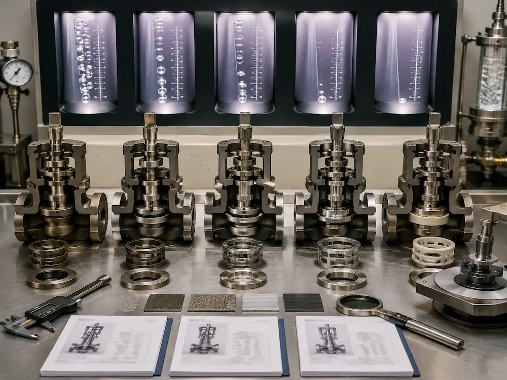
Class VI is frequently described in commercial documents as “bubble tight” or “zero leakage.” These phrases can create incorrect expectations.
Class VI defines a very low allowable leakage rate under a specified production test. It does not prove that no molecule can pass through the seat under every service pressure, temperature, medium and operating history.
Actual service leakage can be influenced by:
- Temperature change after factory testing
- Thermal expansion or contraction of trim parts
- Particles trapped on the seat
- Seat swelling, hardening or chemical attack
- Reduced actuator supply pressure
- Incorrect actuator adjustment
- Flow direction and pressure unbalance
- Erosion, cavitation or flashing damage
- Repeated cycling and long-term seat wear
When the process requires positive isolation for maintenance or safety, the design may require a separate isolation valve, double-block arrangement, bleed connection or another engineered isolation method. A throttling control valve should not automatically be treated as the only maintenance isolation barrier.
Class IV vs Class V vs Class VI
These are the most frequently discussed control valve shutoff classes, but they represent different design and testing approaches.
| Selection Factor | Class IV | Class V | Class VI |
|---|---|---|---|
| Typical seat concept | Metal seat | High-quality metal seat or specially engineered trim | Often resilient, elastomeric or composition seat |
| Temperature capability | Broad when material is suitable | Often selected for demanding high-temperature metal-seat service | Limited by soft-seat or composition-seat material |
| Dirty or abrasive media | May be more tolerant depending on trim design | Requires hardfacing, surface finish and erosion review | Soft seat may be damaged by particles or abrasion |
| Actuator demand | Normal engineered seat load | May require higher and carefully controlled seating force | Must compress the soft seat without overstressing it |
| Main advantage | Practical general-service metal-seat shutoff | Very tight metal-seat performance | Very low production-test leakage |
| Main limitation | Higher allowed leakage than Classes V or VI | More demanding machining, lapping, actuator and test control | Seat material can limit pressure, temperature, chemical resistance and durability |
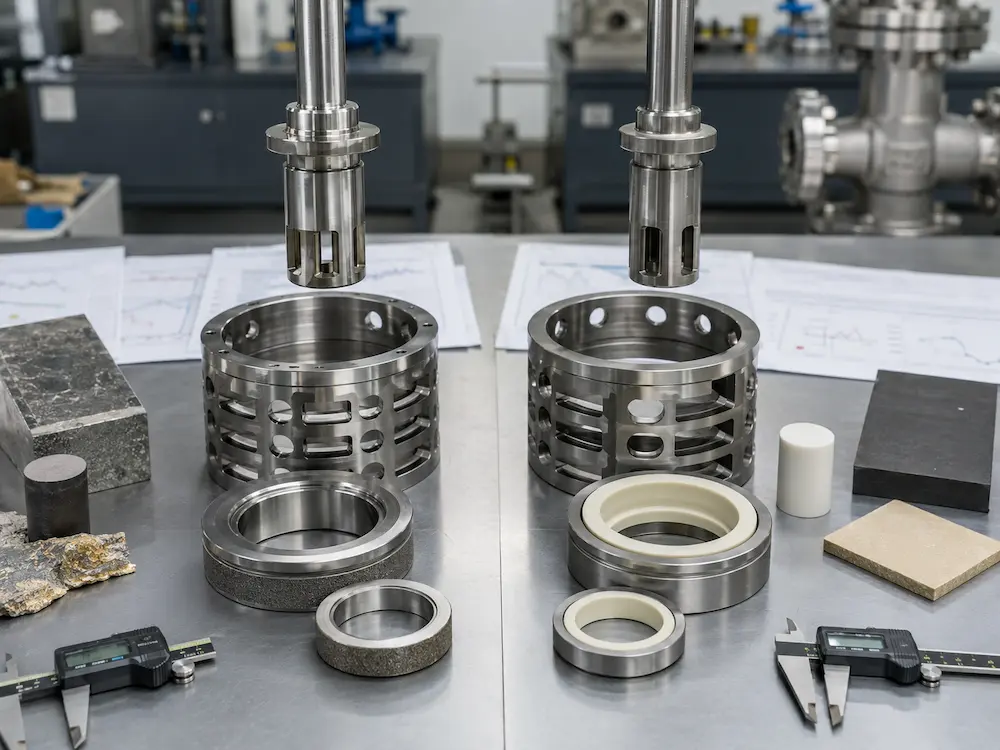
Soft Seat vs Metal Seat for Leakage Class Selection
Metal-Seated Control Valves
Metal seats are commonly selected for high temperature, high pressure drop, abrasive service, steam, flashing, cavitation risk or applications where a soft seat would deform or deteriorate.
Metal-seat tightness depends on:
- Plug and seat geometry
- Machining accuracy and concentricity
- Lapping quality and surface finish
- Hardfacing or coating selection
- Guide alignment
- Stem and actuator alignment
- Required seating force
- Pressure direction and unbalanced force
Class IV is common for general metal-seat control valves. Class V may be required for tighter high-pressure service, but it should be confirmed against the selected body, trim, pressure differential and actuator.
Soft-Seated Control Valves
Soft or composition seats can support very tight shutoff in suitable clean service. Common seat materials may include PTFE-based compounds, elastomers or engineered polymers, depending on the selected design.
The seat must be reviewed for:
- Maximum and minimum temperature
- Chemical compatibility
- Pressure differential
- Extrusion or deformation risk
- Particle damage
- Compression set
- Fire-safe or hazardous-service requirements
Specifying Class VI without identifying the seat material and process condition can create a valve that passes a factory air test but has an unsuitable seat for the actual service.
For trim and seat material decisions, review the Valve Trim Materials Selection Guide.
Why Actuator Sizing Affects Seat Leakage
The seat leakage class applies to the complete valve and actuator package, not only to the valve body.
The actuator must provide sufficient closing thrust or torque under the minimum available utility condition. The calculation should consider:
- Maximum shutoff pressure differential
- Flow direction and unbalanced process force
- Seat load required by the selected class
- Packing and guide friction
- Spring range or actuator output across the complete stroke
- Minimum instrument-air pressure
- Fail-open or fail-close action
- Positioner and bench-set adjustment
Too little force can prevent the required leakage class. Excessive force can damage a soft seat, deform trim parts, increase friction or shorten service life.
Do not solve a leakage problem by increasing actuator force without confirming the valve manufacturer’s allowable seat load and stem force.
For complete package selection, see the Valve Actuator Selection Guide.
Test Conditions That Must Be Confirmed
Two tests described as “Class VI” are not necessarily equivalent if the test conditions differ.
| Test Item | Why It Matters |
|---|---|
| Applicable standard and edition | Defines the class, setup, acceptance method and reporting basis |
| Test medium | Air, nitrogen or water behave differently and use different measurement methods |
| Test pressure differential | Leakage and seating force can change with differential pressure |
| Flow direction | Pressure may assist or oppose seating depending on valve design |
| Valve position and actuator supply | Confirms whether the test uses normal actuator closing force and agreed utility conditions |
| Temperature | Ambient test results do not automatically represent hot or cryogenic service |
| Stabilization and duration | The valve and measuring system need a defined period before acceptance is recorded |
| Measurement method | Volumetric flow, liquid collection or bubble-count methods have different limits and accuracy |
Ambient Test vs Actual Service Condition
Production seat leakage testing is normally a controlled factory acceptance test. It is not a complete simulation of every process condition.
High-Temperature Service
Steam and hot-process valves may experience thermal expansion, guide clearance change, material distortion and different seat contact after heating. The project should identify whether an ambient leakage test is sufficient or whether additional hot-service verification is required.
Cryogenic and Low-Temperature Service
Cold service can change dimensions, seat contact and material behavior. Cryogenic seat leakage should be specified under the applicable low-temperature standard and project procedure rather than inferred from an ambient Class IV, V or VI test.
Dirty, Abrasive or Crystallizing Media
A clean factory test cannot reproduce rust scale, catalyst particles, slurry, crystallization or deposits. When the medium can contaminate the seat, valve body style, flow direction, flushing and maintenance access may be more important than selecting the tightest catalogue class.
Do Not Automatically Specify the Tightest Class
A tighter leakage class may increase valve cost, actuator size, trim complexity, maintenance sensitivity and delivery time. It can also force the use of a soft seat that is unsuitable for the process temperature or medium.
Select the class from the consequence of leakage:
- Can leakage contaminate another product?
- Can it overpressure downstream equipment?
- Can it waste steam, fuel gas or an expensive process fluid?
- Can it create an unsafe reaction or environmental release?
- Does the valve need only throttling, or must it also provide operational shutoff?
- Is a separate isolation valve available?
- Will a soft seat survive the pressure, temperature and medium?
The correct class is the tightest practical requirement justified by the process—not automatically the highest class listed in a template datasheet.
Application-Based Selection Examples
| Application | Possible Starting Point | Additional Review |
|---|---|---|
| General water flow control | Class IV or tighter according to process need | Water quality, seat material, shutoff differential and actuator force |
| High-temperature steam control | Metal-seat Class IV or Class V after review | Temperature, trim hardfacing, thermal growth, pressure drop and noise |
| Clean gas requiring very tight shutoff | Class VI may be considered | Soft-seat compatibility, fire safety, pressure and actual isolation requirement |
| Abrasive slurry | Do not select by class alone | Body style, particle size, erosion, flushing and seat durability |
| Cryogenic liquid or gas | Project-specific cold leakage requirement | Low-temperature test standard, material contraction and extended bonnet design |
Control Valve Leakage Class RFQ Checklist
- Standard and edition: ANSI/FCI 70-2-2021, IEC 60534-4:2021 or the project-specified reference.
- Required leakage class: identify the class explicitly.
- Valve type: globe, angle, rotary, eccentric plug, butterfly or another control valve design.
- Seat construction: metal, hardfaced metal, resilient or composition seat.
- Medium: fluid name, composition, solids and contamination risk.
- Operating and design temperature: include low-temperature or high-temperature cases.
- Maximum shutoff differential pressure: not only normal operating differential.
- Flow direction: flow-to-open, flow-to-close or project-defined direction.
- Fail action: fail-open, fail-close or fail-in-place.
- Minimum actuator supply: air pressure, hydraulic pressure or electrical condition.
- Test medium and pressure: state project requirements when different from the standard default.
- Witness requirement: buyer, third party or document review only.
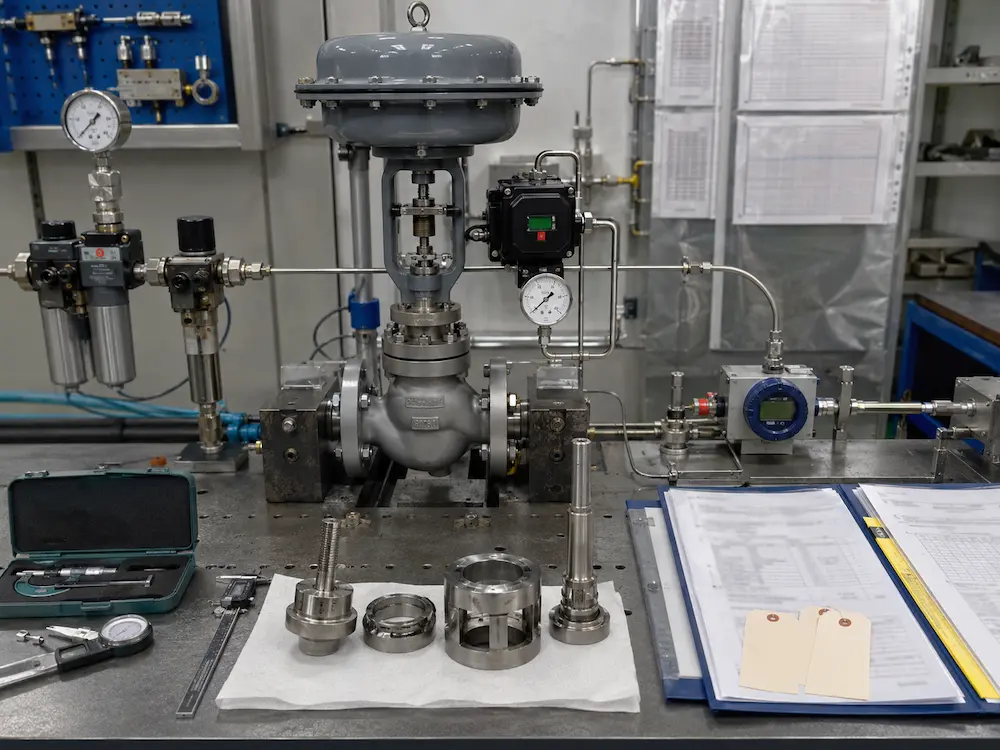
- Required records: test report, calibration record, actuator setting and inspection certificate.
- Special service: cryogenic, oxygen, fire-safe, hazardous, toxic or fugitive-emission requirement.
What Should Appear in the Test Report?
- Valve tag number, model, size and pressure class
- Body and trim identification
- Seat material and leakage class
- Applicable test standard and edition
- Test medium and temperature
- Test pressure differential and flow direction
- Actuator type, supply pressure and fail action
- Measured leakage and acceptance result
- Test duration and measuring method
- Test date, equipment identification and inspector approval
The report should correspond to the exact valve and actuator assembly being shipped. A generic certificate that does not identify the valve tag, class and test condition provides limited project value.
Relationship to Control Valve Sizing and Trim Selection
Leakage class should be confirmed after the basic control valve body and trim concept has been established.
A very tight seat requirement can affect:
- Trim material and seat construction
- Actuator thrust or torque
- Minimum controllable flow
- Friction and deadband
- Temperature capability
- Cavitation and flashing resistance
- Maintenance and spare-parts strategy
For the complete selection sequence, read the Control Valve Selection Guide. Required Cv, predicted travel and operating cases should be established using How to Size a Control Valve.
Confirm the Leakage Requirement Before Quotation
Send Vcore Valve the control valve type, medium, pressure differential, temperature, leakage standard and class, seat preference, actuator fail action and inspection requirements. We can review the valve, trim, seat and actuator as one engineered package.
Related Technical Resources
- Control Valve Selection Guide
- How to Size a Control Valve
- Equal Percentage vs Linear Control Valve
- Valve Trim Materials Selection Guide
- Control Valve Trim Options for Cavitation and Noise Reduction
- Valve Actuator Selection Guide
- Valve Pressure Test Methods
- Industrial Control Valve Products
Technical References
- Fluid Controls Institute — ANSI/FCI 70-2-2021, Control Valve Seat Leakage Testing
- IEC 60534-4:2021 — Inspection and Routine Testing of Industrial-Process Control Valves
- ISA-75 Series — Control Valve Design, Testing and Performance Standards
Frequently Asked Questions
What is a control valve leakage class?
It defines the maximum permitted flow through a closed control valve seat under the test conditions specified by the applicable standard.
Is Class VI control valve leakage equal to zero leakage?
No. Class VI permits a very low measured leakage rate under a specified test. It should not be described as guaranteed absolute zero leakage under every service condition.
What is the difference between Class IV and Class V?
Class IV is a common tighter metal-seat requirement based on rated capacity. Class V uses a more stringent liquid leakage criterion related to pressure differential and seat or port size.
Does Class VI always require a soft seat?
Class VI is commonly associated with resilient or composition seats, but the selected valve design and manufacturer capability must be confirmed. Do not assume every metal-seat valve can achieve Class VI.
Can a control valve replace an isolation valve?
Not automatically. When positive isolation is required for maintenance or safety, the piping design may need a separate isolation valve or engineered double-block arrangement.
Why does the actuator affect leakage class?
The actuator must provide the required seating force or torque at the maximum shutoff differential and minimum available utility supply. Incorrect force or adjustment can prevent the valve from meeting the specified class.
Does an ambient seat test prove cryogenic leakage performance?
No. Cryogenic and low-temperature service requires the applicable cold-test standard and procedure because material contraction and seat behavior can change significantly at low temperature.
What should be included in a control valve leakage specification?
State the standard and edition, leakage class, valve and seat type, medium, maximum shutoff differential, flow direction, temperature, actuator fail action, test medium, witness requirement and documentation.