Control valve sizing should use minimum, normal and maximum flow conditions with the corresponding inlet pressure, outlet pressure, temperature and fluid properties for each case. Cv or Kv determines required flow capacity, but the final valve selection must also check predicted travel, installed flow characteristic, cavitation, flashing, choked flow, velocity, noise and actuator force. Pipeline size alone does not determine the correct control valve size.
A common control valve sizing failure begins with a simple assumption: the pipeline is DN100, so the project selects a DN100 control valve.
The valve passes the required maximum flow, but during normal operation it remains close to the seat. Small stem movements produce large flow changes, the positioner continually corrects the valve position, and the process variable begins to cycle around the setpoint.
The valve is not necessarily defective. It may simply have more flow capacity than the process can use during normal operation.
Correct sizing starts with the process conditions—not the pipeline diameter. This article explains how to size a control valve using Cv or Kv, minimum, normal and maximum flow cases, corresponding pressure conditions and predicted valve travel.
Start with a Control Valve Sizing Worksheet
Before selecting a valve model, prepare one sizing worksheet containing every operating condition the valve must control.
Do not provide one maximum flow rate together with unrelated design pressures. Each flow case must have its own corresponding inlet pressure, outlet pressure and temperature.
| Sizing Item | Minimum Case | Normal Case | Maximum Case |
|---|---|---|---|
| Flow rate | Lowest stable process demand | Most frequent operating flow | Highest required continuous or peak flow |
| Inlet pressure | Pressure when minimum flow occurs | Pressure at normal operation | Pressure when maximum flow occurs |
| Outlet pressure | Corresponding downstream pressure | Corresponding downstream pressure | Corresponding downstream pressure |
| Temperature | Minimum-case fluid temperature | Normal operating temperature | Maximum-case fluid temperature |
| Valve objective | Stable low-flow control | Stable routine operation | Adequate maximum capacity |
Startup, shutdown, bypass, cleaning, regeneration or emergency operating cases should be added separately when they impose different flow or pressure conditions.
Liquid Data Required
- Fluid name and chemical composition
- Minimum, normal and maximum flow rate
- Inlet and outlet pressure for every flow case
- Operating temperature for every flow case
- Density or specific gravity
- Vapor pressure at the operating temperature
- Critical pressure where required by the selected sizing method
- Viscosity for viscous liquids
- Solids content, particle size and abrasive characteristics
Gas and Steam Data Required
- Gas composition or steam condition
- Minimum, normal and maximum mass or volume flow
- Absolute inlet and outlet pressure for every case
- Inlet temperature
- Molecular weight or gas specific gravity
- Compressibility factor
- Ratio of specific heats where required
- Steam quality or degree of superheat
Gas and steam sizing normally requires absolute pressure. Clearly identify whether submitted values are barg, bara, psig or psia.

What Cv and Kv Actually Mean
Cv and Kv are flow-capacity coefficients. They represent the capacity of a particular valve and trim at a defined opening under specified reference conditions.
They do not directly identify:
- The nominal pipeline size
- The valve pressure class
- The actuator force
- The seat leakage class
- The suitability of the valve for cavitation or flashing
Basic Metric Liquid Screening Equation
For a turbulent, non-choked, water-like liquid without significant piping correction, a preliminary metric estimate can be expressed as:
Kv = Q × √(SG / ΔP)
- Kv: metric flow coefficient
- Q: liquid flow rate in m³/h
- SG: liquid specific gravity relative to water
- ΔP: pressure drop across the valve in bar
Basic US Liquid Screening Equation
Using US customary units, the corresponding preliminary equation is:
Cv = Q × √(SG / ΔP)
- Cv: US flow coefficient
- Q: liquid flow rate in US gallons per minute
- SG: liquid specific gravity relative to water
- ΔP: pressure drop across the valve in psi
The equation looks the same, but the units are different. Cv and Kv must not be exchanged without conversion.
For practical conversion:
- Cv ≈ 1.156 × Kv
- Kv ≈ 0.865 × Cv
These simplified equations are useful for explaining the basic relationship between flow, specific gravity and pressure drop. Final sizing should use an IEC 60534-2-1 or ANSI/ISA-75.01.01 method with the selected valve coefficients and all applicable correction factors.
Why Exact Sizing Requires More Than the Basic Equation
Installed control valve sizing may need to account for:
- Liquid pressure recovery and choked flow
- Cavitation or flashing
- Gas expansion and compressibility
- Critical pressure ratio
- Valve-specific pressure recovery factors
- Reducers, expanders and other attached fittings
- Non-turbulent or low-Reynolds-number flow
- High viscosity
- Multi-stage trim
- Outlet velocity and aerodynamic noise
The manufacturer must therefore use the actual coefficients of the selected valve body and trim, not a generic coefficient taken from an unrelated product.
Why Minimum, Normal and Maximum Flow Must Be Sized Separately
The required Cv or Kv changes whenever flow or pressure drop changes. The maximum-flow case does not automatically produce the maximum required coefficient.
For example, the process may require maximum flow when the available pressure drop across the valve is relatively low. This can produce the highest required Cv.
At minimum flow, the upstream pressure may remain high while downstream demand falls. The valve then has a larger pressure drop but must regulate a much smaller flow without operating too close to the seat.
Minimum Flow Case
The minimum case checks whether the valve can regulate the lowest required flow with stable and repeatable movement.
Important questions include:
- Will the valve operate extremely close to the seat?
- Is the required flow below the controllable range of the selected trim?
- Will seat friction and packing friction dominate small position changes?
- Is a reduced trim, characterized trim or split-range arrangement required?
Normal Flow Case
The normal case deserves the greatest attention because it represents where the valve may spend most of its operating life.
The valve should provide useful travel and predictable installed gain at this condition, rather than operating continually near the closed or fully open position.
Maximum Flow Case
The maximum case checks whether the valve has enough capacity while retaining a reasonable allowance for process variation and sizing uncertainty.
A valve should not be enlarged automatically simply to create a very large spare capacity. Excessive spare capacity can reduce normal-load controllability.
Pipeline Size Does Not Determine Control Valve Size
Pipeline diameter is selected from system velocity, pressure loss, flow demand, mechanical design and economic considerations.
Control valve size is selected from:
- Required Cv or Kv
- Available pressure drop
- Predicted operating travel
- Valve body and trim capacity
- Inlet and outlet velocity
- Cavitation, flashing and noise risk
- Mechanical connection and piping layout
A control valve may therefore be smaller than its connected pipeline. Proper reducers and expanders can be used when the resulting velocity, noise, pressure recovery and piping loads remain acceptable.
The effect of attached reducers and expanders must be included in installed sizing when applicable.
When a Line-Size Control Valve May Be Too Large
A line-size valve is likely to be oversized when:
- The control valve receives only a small portion of the total system pressure drop
- The valve body has a high rated Cv relative to process demand
- The selected rotary valve has much greater capacity than a globe valve of the same nominal size
- The process normally operates far below design flow
- A future capacity allowance has been added repeatedly by different project disciplines
Required Cv Is Not the Same as Valve Travel
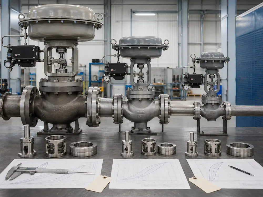
After calculating the required Cv or Kv for each operating case, the next step is to compare those values with the selected valve’s capacity-versus-travel curve.
A valve with a rated Cv of 100 does not necessarily provide Cv 50 at 50% travel.
The relationship depends on:
- Inherent flow characteristic
- Trim geometry
- Valve body style
- Selected reduced or full-size trim
- System pressure losses
- Pressure drop available across the valve at each flow
Linear Characteristic
A linear trim produces approximately equal increments of flow coefficient for equal increments of valve travel under a constant pressure drop across the valve.
This does not guarantee that the installed process flow will be linear with travel, because the pressure drop across the valve often changes as system flow changes.
Equal-Percentage Characteristic
An equal-percentage trim produces approximately the same percentage change in the current flow coefficient for equal increments of travel under the defined test condition.
It is frequently considered where the process requires a wide flow range or where the valve’s share of total system pressure drop changes substantially.
The selected trim characteristic can change predicted travel and installed process response. Read Equal Percentage vs Linear Control Valve before confirming the final trim curve.
Installed Characteristic and Installed Gain
The installed characteristic describes the actual relationship between valve travel and process flow after the valve is connected to the piping system.
Installed gain describes how much the flow changes for a given change in valve travel. Excessively high or low installed gain can make control-loop tuning and stability more difficult.
A fixed rule such as “every valve must operate between 20% and 80% travel” should not replace an installed sizing review. Avoid continual operation extremely close to the seat or full opening, but determine the acceptable range from the selected trim, process dynamics, rangeability and manufacturer sizing result.
Oversized, Correctly Sized and Undersized Valves
| Review Item | Oversized Valve | Correctly Sized Valve | Undersized Valve |
|---|---|---|---|
| Normal travel | Often remains close to the seat | Uses a practical part of the available stroke | Frequently operates near full opening |
| Minimum-flow control | May be unstable or too sensitive | Maintains usable movement and repeatability | May control minimum flow but lacks maximum capacity |
| Maximum-flow capacity | Large unused capacity | Meets demand with a justified allowance | Cannot meet required maximum flow |
| Control response | Small travel changes may create large flow changes | Predictable response across required conditions | Controller may demand more travel than is available |
| Typical symptom | Hunting, cycling and trim wear near the seat | Stable process control after proper tuning | Full-open valve with insufficient process flow |
| Corrective action | Reduced trim, smaller body or revised valve type | Confirm final body, trim and actuator package | Larger capacity, revised pressure allocation or parallel arrangement |
If the installed valve repeatedly cycles around the operating point, sizing may be only one possible cause. Use our Control Valve Hunting Troubleshooting Guide to compare controller command, actual travel, stiction, air supply, positioner response and process-loop behavior before replacing the valve.
Worked Liquid Sizing Example
The following simplified example demonstrates why three operating cases must be checked. It is not a substitute for final IEC or ISA sizing.
Process Data
- Fluid: water-like process liquid
- Specific gravity: 0.98
- Flow units: m³/h
- Pressure-drop units: bar
- Preliminary equation: Kv = Q × √(SG / ΔP)
| Operating Case | Flow Q | Valve ΔP | Preliminary Required Kv |
|---|---|---|---|
| Minimum | 15 m³/h | 2.4 bar | 9.6 |
| Normal | 45 m³/h | 1.6 bar | 35.2 |
| Maximum | 72 m³/h | 1.0 bar | 71.3 |
What the Preliminary Results Show
The maximum-flow case requires the highest preliminary Kv because the available pressure drop is lowest at that condition.
Suppose a candidate trim has a rated Kv of 90. The preliminary required coefficients represent approximately:
- 10.7% of rated Kv at minimum flow
- 39.1% of rated Kv at normal flow
- 79.2% of rated Kv at maximum flow
These percentages are not valve travel percentages. Actual travel must be obtained from the selected trim’s capacity curve and installed sizing calculation.
The sizing engineer must now determine:
- Whether the selected characteristic provides stable minimum-flow travel
- Whether normal flow falls in a useful operating region
- Whether maximum flow can be achieved without unacceptable velocity or severe-service risk
- Whether a rated Kv of 90 is appropriate or whether reduced trim, a different characteristic or another body size is preferable
Additional Liquid Checks
Before final selection, the calculation must include:
- Vapor pressure and liquid critical pressure
- Valve pressure-recovery factor
- Choked-flow pressure drop
- Cavitation or flashing assessment
- Reducer and expander correction
- Inlet and outlet velocity
- Viscosity and Reynolds-number correction where applicable
If cavitation, flashing or severe pressure reduction is identified, review available control valve trim options for cavitation and noise reduction.
Steam and Gas Sizing Requires Compressible-Flow Calculations
The simple liquid equation should not be used for gas or steam sizing.
Compressible-flow calculations must address density changes as the fluid expands through the valve. The calculation may also need valve-specific factors for pressure ratio, expansion, choked flow and attached fittings.
Example Steam Sizing Dataset
| Operating Case | Steam Flow | Inlet Pressure | Outlet Pressure | Temperature |
|---|---|---|---|---|
| Minimum | 2,000 kg/h | 16 barg / 17 bara | 10 barg / 11 bara | 320°C |
| Normal | 6,500 kg/h | 16 barg / 17 bara | 8 barg / 9 bara | 320°C |
| Maximum | 10,000 kg/h | 16 barg / 17 bara | 5 barg / 6 bara | 320°C |
This dataset allows the sizing engineer to calculate the required coefficient and predicted travel for each case while also reviewing:
- Whether compressible flow becomes choked
- Valve outlet velocity
- Aerodynamic noise
- Trim exit velocity
- Body and trim temperature limits
- Required actuator thrust
- Downstream pipe size and reducer arrangement
A valve that has sufficient rated Cv may still be unsuitable if the outlet velocity, noise or trim energy is excessive.
For applicable products, review the Steam Control Valve. Boiler applications may also require a dedicated Boiler Feedwater Control Valve or Spray Water Control Valve.
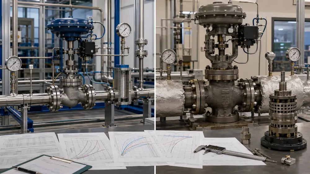
Sizing Must Identify Severe-Service Conditions
A sizing calculation should do more than return one required Cv. It should identify whether the selected valve will be exposed to destructive or limiting fluid behavior.
Liquid Choked Flow
Liquid flow becomes choked when increasing the pressure difference no longer produces the expected increase in flow. This may be associated with vapor formation inside the valve.
A larger actuator cannot correct choked flow because the limiting condition is fluid-dynamic rather than mechanical.
Cavitation
Cavitation occurs when vapor bubbles form at the valve restriction and collapse after pressure recovery.
Potential results include:
- Trim and body pitting
- Noise and vibration
- Seat damage
- Loss of flow capacity
- Damage to downstream piping
Flashing
Flashing occurs when liquid vaporizes through the valve and remains partly vaporized downstream.
Because the vapor does not collapse back into liquid immediately, the design must manage two-phase velocity, outlet direction and erosion rather than treating flashing as ordinary cavitation.
Gas and Steam Choked Flow
Compressible flow can become choked when the pressure ratio reaches the limiting condition for the selected valve and trim.
After this point, reducing downstream pressure further does not produce the proportional capacity increase expected from an unchoked equation.
Noise and Velocity
A valve may satisfy the Cv requirement while producing unacceptable:
- Aerodynamic noise
- Hydrodynamic noise
- Outlet Mach number
- Pipe-wall vibration
- Trim vibration
- Erosion velocity
High-pressure applications should be reviewed using an appropriate High Pressure Control Valve body and trim configuration rather than only increasing the pressure class of a standard valve.
Reduced Trim, Full-Size Trim or a Different Valve Body?
When the pipeline connection size is fixed but the required Cv is relatively low, reduced trim may improve controllability without changing the valve body connection size.
Reduced Trim May Be Useful When
- The pipeline size is required for mechanical or future system reasons
- Normal flow requires a much lower Cv than the full-size trim provides
- A smaller valve body would create excessive reducer or outlet velocity problems
- Future capacity may be handled by changing trim rather than replacing the body
A Smaller Valve Body May Be Better When
- The line-size valve remains severely oversized even with reduced trim
- A smaller body provides better trim geometry and actuator matching
- The reducers and installed velocity remain acceptable
- Weight, space and cost can be reduced without increasing severe-service risk
A Different Valve Style May Be Required When
- A globe valve cannot pass solids without blockage
- A rotary valve provides more appropriate capacity and flow path
- An angle valve better directs flashing or erosive outlet flow
- Multi-stage trim is required for severe pressure reduction
- Large line size makes a compact rotary valve more practical
Review the main Control Valve Selection Guide when the sizing result indicates that the body style, trim or actuator concept should be reconsidered.
Actuator Sizing Is Separate from Cv Sizing
Cv determines flow capacity. The actuator must provide the force or torque required to move the selected valve and achieve the specified shutoff under process conditions.
Actuator sizing should consider:
- Process force acting on the plug, disc or rotary closure element
- Valve pressure unbalance
- Seat load required for the specified leakage class
- Packing and guide friction
- Valve stroke or rotary travel
- Minimum available air, hydraulic pressure or electrical supply
- Fail-open, fail-close or fail-in-place requirement
- Required stroking time
An actuator with greater thrust does not increase the maximum Cv of the selected valve trim.
For the complete actuator review, use the Valve Actuator Selection Guide.
Control Valve Sizing Output Required Before Purchase
A professional sizing result should provide more than the selected nominal valve size.
| Sizing Output | What the Buyer Should Review |
|---|---|
| Selected valve and trim | Body style, nominal size, port size and trim construction |
| Rated Cv or Kv | Capacity of the selected trim at full rated travel |
| Required coefficient | Required Cv or Kv for every operating case |
| Predicted travel | Expected valve position at minimum, normal and maximum flow |
| Flow regime | Turbulent, non-turbulent, choked, cavitating, flashing or compressible condition |
| Noise and velocity | Predicted sound level, outlet velocity and pipe-size suitability |
| Actuator requirement | Required thrust or torque, fail action and minimum utility condition |
| Assumptions | Fluid data, units, pressure basis, fittings and sizing-standard assumptions |
Do not approve the valve solely from the rated Cv shown in a catalogue. Confirm that the sizing report corresponds to the exact body, trim, characteristic and actuator being offered.
Control Valve Sizing Data Sheet for RFQ
Provide the following information with the inquiry:
- Control function: flow, pressure, temperature, level or another variable.
- Medium: name, composition, concentration and physical phase.
- Minimum flow: with corresponding inlet pressure, outlet pressure and temperature.
- Normal flow: with corresponding inlet pressure, outlet pressure and temperature.
- Maximum flow: with corresponding inlet pressure, outlet pressure and temperature.
- Fluid properties: density, vapor pressure, viscosity, molecular weight, compressibility or steam condition.
- Pipeline: pipe size, schedule, material and connection standard.
- Valve pressure rating: design pressure, design temperature and required class.
- Flow characteristic: if specified by the project.
- Seat leakage: required standard and leakage class.
- Known risks: cavitation, flashing, noise, erosion, vibration, solids or crystallization.
- Actuator: pneumatic, electric or project-specified type.
- Fail position: fail-open, fail-close or fail-in-place.
- Control signal: command, feedback and communication requirements.
- Environment: ambient temperature, enclosure and hazardous-area classification.
- Documentation: sizing report, drawing, certificates, inspection and calibration records.
If some fluid properties are unavailable, provide the medium name, composition, pressure and temperature so the missing data can be identified before quotation.
Submit Your Control Valve Sizing Data
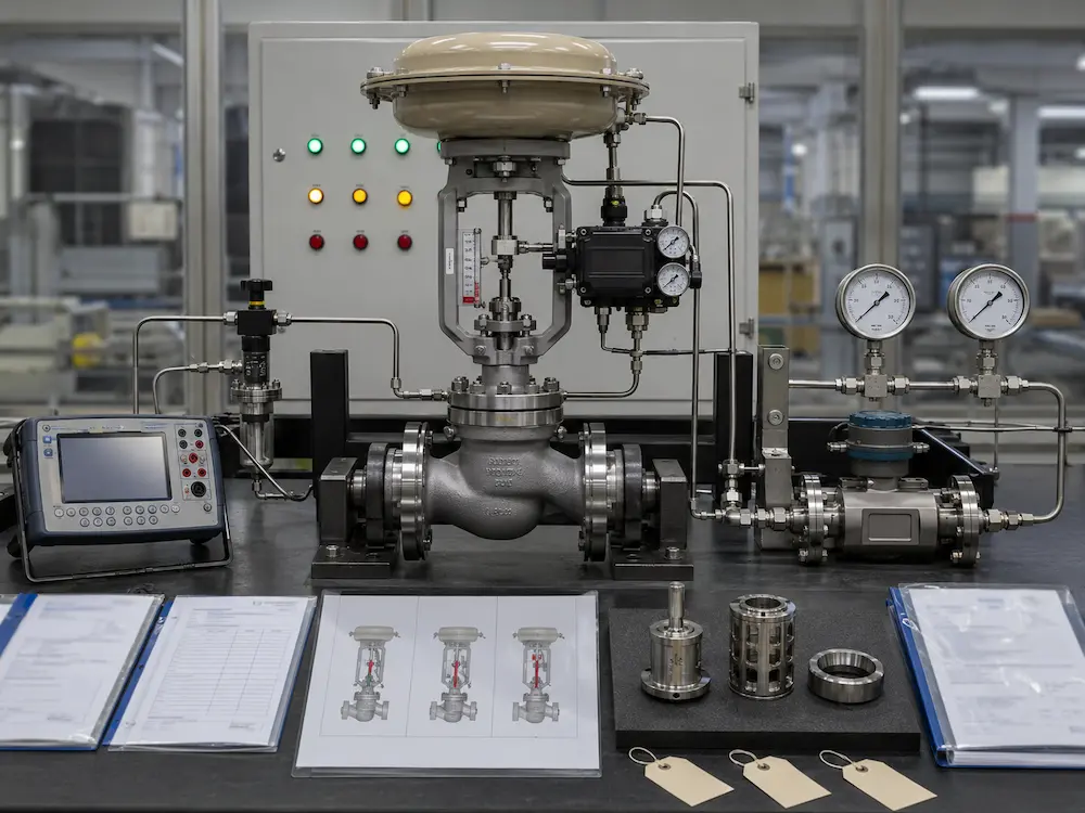
Send Vcore Valve the minimum, normal and maximum flow cases, corresponding inlet and outlet pressures, temperature, medium properties, control signal and fail position. The valve body, Cv or Kv, trim, actuator and severe-service conditions can then be reviewed as one package.
Related Control Valve Resources
- Control Valve Selection Guide
- Industrial Control Valve Products
- High Pressure Control Valve
- Steam Control Valve
- Boiler Feedwater Control Valve
- Spray Water Control Valve
- Control Valve Trim Options for Cavitation and Noise Reduction
- Valve Actuator Selection Guide
- Valve Pressure-Temperature Rating Guide
Technical Basis
- IEC 60534-2-1 — Flow-capacity sizing equations for installed control valves
- ANSI/ISA-75.01.01 — Control valve flow-capacity sizing equations
- Emerson — Control Valve Sizing Procedure
- ISA — Using Control Valve Installed Gain Calculations
Frequently Asked Questions
Can I size a control valve using only the pipe size?
No. Control valve size should be determined from minimum, normal and maximum flow conditions, corresponding pressure drop, fluid properties, required Cv or Kv, predicted travel and severe-service conditions.
What is the difference between Cv and Kv?
Cv and Kv are flow coefficients expressed using different unit systems. Cv normally uses US gallons per minute and psi, while Kv normally uses cubic metres per hour and bar. Approximately, Cv equals 1.156 times Kv.
Why are minimum, normal and maximum flow rates required?
Each operating case can have a different pressure drop and required coefficient. The three cases show whether the valve can control minimum flow, operate stably at normal flow and provide enough maximum capacity.
What happens when a control valve is oversized?
An oversized valve may operate close to the seat during normal service. Small changes in travel can then produce large flow changes, causing unstable control, cycling and accelerated trim wear.
What happens when a control valve is undersized?
An undersized valve may reach full travel without passing the required maximum flow. Increasing actuator force cannot increase the rated capacity of the selected trim.
What valve travel should be targeted?
There is no universal travel percentage suitable for every control valve. The acceptable operating region should be determined from the selected trim characteristic, installed gain, minimum-flow controllability, maximum capacity and process dynamics.
Can the simple liquid Cv equation be used for steam?
No. Steam and gas require compressible-flow equations using absolute pressure, temperature and the appropriate valve-specific expansion and pressure-ratio factors.
What information is needed for a control valve quotation?
Provide the medium, minimum, normal and maximum flow conditions, corresponding inlet and outlet pressures, temperature, fluid properties, pipe data, leakage requirement, actuator, fail position, signal and inspection requirements.