Quick Decision
Ball valve flow control issues are not all maintenance faults. First identify the duty: a standard full-bore ball valve is mainly an isolation device, while a V-port or segmented-ball control valve is built for modulation. If a healthy on-off valve is forced to regulate flow near the closed position, repeated calibration and seat replacement will not correct the selection problem.
Start with evidence from the process, valve and actuator. Record minimum, normal and maximum flow; upstream and downstream pressure; temperature; medium properties; commanded position; actual travel; and the point at which noise, hunting or leakage begins.
Is the Valve Wrong for the Duty?
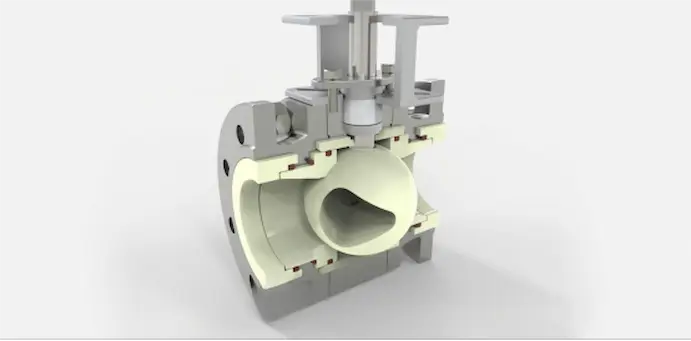
A conventional full-bore ball valve offers low pressure loss when fully open and reliable quarter-turn isolation. Its flow response, however, can be too abrupt for fine control: a small movement near the seat may produce a large change in effective flow area. A characterized V-port or segmented ball uses intentional geometry to produce a more controllable relationship between travel and flow.
When investigating ball valve flow control issues, the question is not simply “Can a ball valve throttle?” but “Does this valve’s trim, sizing, actuator and control characteristic match the required operating range?” ISA-75.11.01 defines methods for evaluating inherent flow characteristics and rangeability, while ISA-75.13.01 addresses positioner performance factors such as deadband, hysteresis and response time. See the ISA 75 standards overview.
Read the Symptom Before Opening the Valve
Ball valve flow control issues often leave a repeatable pattern in operating data. Match the symptom to measured evidence before disassembly.
| Observed symptom | Evidence to collect | Probable cause | Next decision |
|---|---|---|---|
| Little response, then a sudden flow jump | Command and actual travel at low opening | Oversized valve, quick-opening geometry, stiction or linkage play | Verify travel; recalculate Cv and required characteristic |
| Actuator hunts around setpoint | Input signal, feedback trend and air supply | Positioner deadband, poor tuning, unstable process or excessive valve gain | Test the loop before replacing trim |
| Noise and vibration at part opening | P1, P2, temperature and fluid vapor pressure | High velocity, cavitation, flashing or choked flow | Perform a hydraulic review; do not treat it as a simple seat fault |
| Low flow at full command | Actual shaft travel and line differential pressure | Restricted bore, deposits, incorrect travel stop, undersizing or upstream restriction | Separate line loss from valve capacity |
| Leakage when closed | Leak rate, seat condition and closing torque | Particles, erosion, incompatible seat, ball damage or incomplete travel | Clean, repair or reselect according to damage and duty |
For a broader failure investigation, use our valve problem root-cause guide. When movement is intermittent or torque rises over time, compare the evidence with valve sticking causes and corrective actions.
How to Diagnose Ball Valve Flow Control Issues
1. Process and Hydraulic Conditions
For persistent ball valve flow control issues, use actual operating data rather than the pipe size alone. Check minimum, normal and maximum flow; upstream and downstream pressure at each condition; fluid temperature; density or specific gravity; vapor pressure for liquids; and compressibility data for gas. Valve sizing should use a recognized method such as ISA-75.01 control valve sizing equations together with verified manufacturer coefficients.
An oversized control valve often spends most of its life close to the seat, where gain is high and available travel is small. An undersized valve may reach full travel without meeting demand. High differential pressure can also create cavitation or choked flow, so increasing actuator force does not necessarily increase capacity. Confirm that body, trim and seat limits remain acceptable at temperature using the valve pressure-temperature rating guide.
2. Valve and Mechanical Condition
Isolate, depressurize and verify zero energy before inspection. Confirm the ball or segmented trim reaches its specified travel, the shaft and coupling do not slip, and travel stops have not moved. Inspect seats and sealing surfaces for embedded solids, scoring, chemical swelling, erosion or thermal damage. For directional V-port and unidirectional seat designs, confirm the installation arrow and preferred pressure direction against the manufacturer’s drawing.
Do not diagnose shutoff from appearance alone. Record the test medium, differential pressure, test direction and allowable leakage. Our valve sealing performance guide explains why shell rating, seat leakage and fugitive-emission requirements are separate checks.
3. Actuator, Positioner and Control Signal
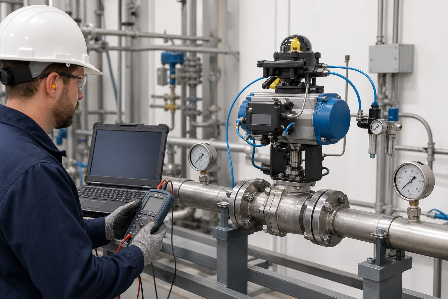
For ball valve flow control issues linked to automation, trend commanded position and actual feedback through several small steps in both opening and closing directions. A gap between them can reveal deadband, hysteresis, calibration error, loose coupling or insufficient torque. For pneumatic systems, check clean, dry supply pressure under movement, not only at rest. For electric actuators, check supply voltage, duty cycle, limit settings, torque switches and local/remote logic.
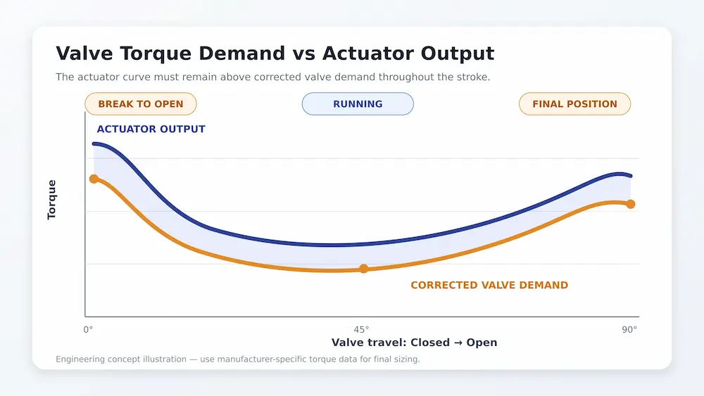
Required actuator torque is not constant through a quarter turn. Break torque, running torque and end-to-close torque can differ, and process differential pressure adds load. Compare the valve’s worst-case torque demand with the actuator’s available output at the minimum air pressure or supply voltage. Use the actuator torque sizing guide for the full calculation workflow.
Repair, Tune or Reselect?
| Finding | Appropriate action | Why |
|---|---|---|
| Dirty seat, blocked impulse line or shifted calibration | Clean, calibrate and retest | The valve concept may still be correct |
| Minor replaceable seat or packing wear | Repair with verified materials and dimensions | Restores the specified assembly without changing duty |
| Loose coupling, travel-stop error or inadequate air supply | Correct the actuator package and prove full stroke | The valve may not be receiving the commanded position |
| Chronic operation below about 10–15% travel | Recalculate sizing and consider reduced trim or another valve | The installed valve may provide too much capacity near closed |
| Recurring cavitation, severe erosion or flashing damage | Redesign the pressure-drop strategy and select suitable trim/materials | Repeated seat replacement leaves the hydraulic cause unchanged |
| Standard on-off ball valve used for demanding modulation | Consider a V-port/segmented ball or another control-valve style | The required characteristic and rangeability must be designed in |
When ball valve flow control issues return after repair, verify that the valve architecture still matches the duty. Replacement is justified when the pressure boundary is damaged, critical parts cannot be restored to specification, or the valve architecture is wrong for the duty. The repair-or-replace decision guide helps document that choice.
What to Put in the RFQ
A useful control-ball-valve inquiry should include:
- minimum, normal and maximum flow, plus required turndown;
- upstream and downstream pressure at all three flow conditions;
- medium, concentration, solids size/content, density, viscosity and vapor pressure where relevant;
- minimum, normal, design and upset temperature;
- line size, schedule, end connection, pressure class and piping material;
- required inherent characteristic, shutoff direction and allowable leakage class;
- fail action, stroke time, signal, position feedback and available air pressure or electrical supply;
- body, trim, seat, gasket and bolting requirements, including corrosion or sour-service constraints;
- hazardous-area classification, inspection plan, test standard and required certificates.
Supplying only valve size, pressure class and medium forces the manufacturer to guess at the control duty. For an engineering review and quotation, send Vcore Valve your operating cases and project requirements. We can check valve style, Cv, characteristic, materials and actuator margin before preparing the proposal.
Frequently Asked Questions
Can a standard ball valve be used for flow control?
It can provide coarse manual throttling in some noncritical services, but stable automated modulation normally requires verified sizing and a characterized design such as a V-port or segmented ball. Suitability depends on the operating range, differential pressure, medium, seat design and required control accuracy.
Why does flow change suddenly near the closed position?
The valve may be oversized or have a quick-opening characteristic, leaving too little usable travel at normal flow. Mechanical stiction or positioner deadband can produce a similar symptom, so compare commanded position with actual shaft travel before changing the valve.
Why does an actuated ball valve hunt?
Possible causes include excessive valve gain, poor loop tuning, unstable supply pressure, positioner deadband, loose linkage, noisy feedback or an actuator that cannot overcome the required torque consistently.
When is replacement better than another repair?
Ball valve flow control issues that repeat because of incorrect sizing call for reselection. Reselect the valve when failures repeat because of incorrect sizing, unsuitable flow characteristic, cavitation, erosion, incompatible materials or insufficient actuator margin. Repair is more appropriate when the design is correct and the fault is limited to contamination, calibration or replaceable wear parts.