Quick overview
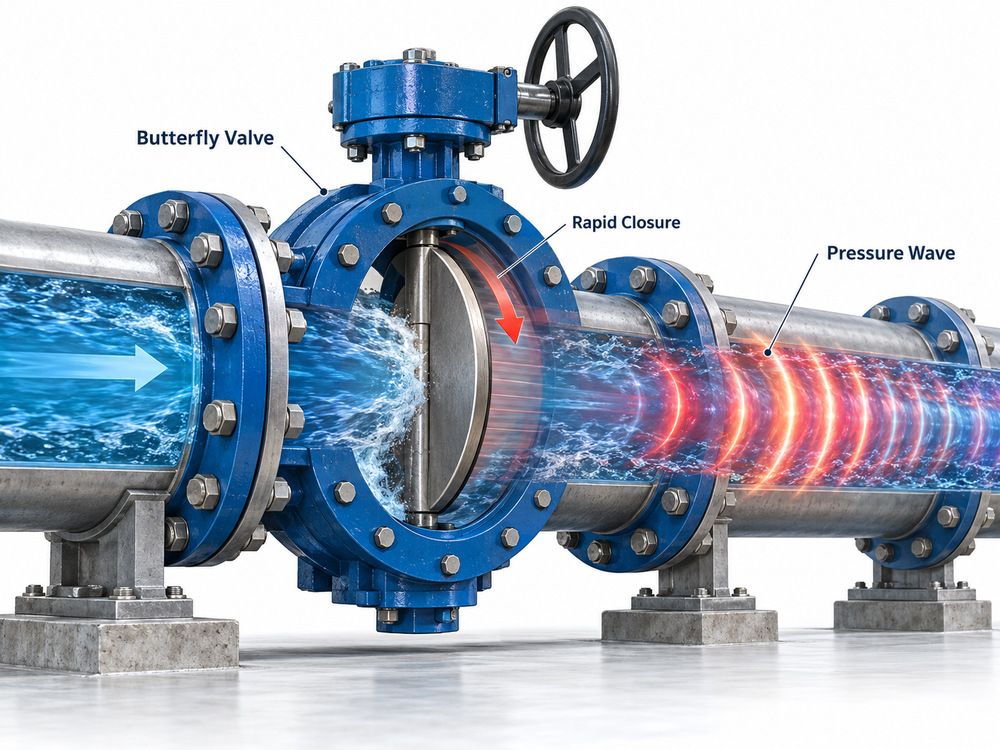
Water hammer in butterfly valves occurs when changes in flow velocity generate pressure waves in a pipeline. Rapid closure is one possible trigger, but pump trips, check-valve slam and reflected waves can be equally important. Preventing damage requires more than ordering a slow actuator: designers must assess the complete hydraulic system, define a suitable valve-closing profile and verify maximum and minimum transient pressures. This guide covers practical warning signs, a transparent calculation example and the specifications buyers should send with a butterfly-valve enquiry.
Imagine a coastal pumping station at the end of a busy commissioning day. A large discharge butterfly valve receives a close signal; seconds later, the pipework shudders. Was the actuator too fast, the check valve too late or the entire pump-trip sequence poorly coordinated? The answer rarely sits on one valve datasheet. Understanding water hammer in butterfly valves starts with system hydraulics rather than a blanket rule such as “close in 30 seconds”.
What Causes Water Hammer in Butterfly Valves?
Water hammer is a hydraulic transient: an abrupt change in liquid velocity produces a travelling pressure disturbance. Water and pipe walls have finite elasticity, so pressure waves move through the network and reflect at tanks, bends, valves, branches and pumps. These interactions can create overpressure, sub-atmospheric pressure or vapour cavities that collapse later. The audible bang is only one symptom; some damaging events are practically silent.
A butterfly valve is a quarter-turn device, typically moving its disc through approximately 90 degrees. Its hydraulic resistance does not change linearly with disc angle. Consequently, an actuator that turns at constant angular speed may not deliver a constant rate of flow reduction. A relatively short section near closure can dominate the transient, depending on valve characteristic and system duty.
Three recurring engineering pain points
- Unexpected shutdown pressure: a pipeline designed around steady operating pressure experiences a temporary surge above the assumed design envelope.
- Misleading actuator timing: an advertised full-stroke closing time ignores the actual disc-angle-versus-time curve and the speed of flow reduction.
- Pump-trip uncertainty: valve movement, reverse flow, air pockets and non-return valve behaviour combine in a sequence that a static pressure test cannot reproduce.
Pressure Waves, Closure Time and the Joukowsky Equation
A useful screening relationship is the Joukowsky equation, ΔP = ρaΔV in magnitude, where ΔP is the initial pressure change in pascals, ρ is liquid density in kg/m³, a is pressure-wave speed in m/s and ΔV is the change in velocity in m/s. Its sign depends on whether velocity rises or falls. This is an idealised estimate for a rapid change, not a prediction of every pressure maximum across a complicated pipeline.
For illustration, assume water density of 1,000 kg/m³, wave speed of 1,000 m/s and a rapid velocity reduction of 1.5 m/s. The initial pressure-rise magnitude is 1,500,000 Pa, approximately 15 bar. Added to a hypothetical 8 bar local operating pressure, this suggests an initial pressure of roughly 23 bar. These are deliberately illustrative inputs, not design results or a recommendation to select a particular valve pressure class.
A further screening measure is the round-trip wave travel time, 2L/a, where L is the relevant hydraulic path length. For a simplified 1,000 m pipe with a wave speed of 1,000 m/s, the travel time is 2 seconds. Closure over a shorter period can behave as a rapid event. A longer time may reduce the first surge, but cannot guarantee safety: complex reflection patterns, pump characteristics and vapour-cavity collapse can produce later peaks.
For a fuller explanation, see the engineering reference on the instantaneous water-hammer equation and its discussion of limitations in branching systems. Both are standard editorial links without a nofollow attribute.
Three Practical Ways to Prevent Butterfly Valve Water Hammer
1. Engineer the closing profile, not just the total time
Specify the required disc position against time, particularly over the angles where hydraulic resistance increases sharply. An electric, pneumatic or hydraulic actuator may need controlled deceleration, variable-speed operation or staged closure. The correct shape depends on the manufacturer’s valve flow characteristic and transient-study findings. Faster closure is not always worse in every scenario: the optimum sequence must also consider reverse flow and emergency isolation requirements.
Obtain actuator torque output throughout the stroke and compare it with valve breakaway, dynamic, running and seating torque. A slow programme that stalls under differential pressure is not successful surge protection. Where appropriate, review the hydraulic double-flanged butterfly valve and the electric-actuated flanged butterfly valve as product configurations—not as pre-approved surge-control solutions.
2. Coordinate pump, check valve and isolation valve
In pumping installations, a power failure can decelerate the pump before a motor-operated isolation valve begins closing. Flow may reverse, a check valve may close abruptly and pressure waves may move through the suction and discharge headers. Review the time sequence, pump inertia, non-return valve dynamics, operating levels and any standby-pump start. A pump-station valve selection guide explains the broader valve arrangement; this article concentrates on the transient itself.
3. Model and protect the complete network
Use a suitable transient analysis, commonly based on the method of characteristics or another validated solver, to test normal closure, pump trip, power loss, emergency shutdown and start-up. Examine maximum and minimum pressure along the entire line, not merely at the butterfly valve. Depending on the results, possible mitigations include surge vessels, appropriately engineered air valves, controlled pump ramping, relief systems or altered valve sequences. Device sizing and locations must be established by qualified hydraulic designers.
The AWWA standards catalogue identifies C504 and C519 for relevant waterworks butterfly-valve categories. Such valve standards support equipment specification; they do not remove the need for project-specific hydraulic transient verification.
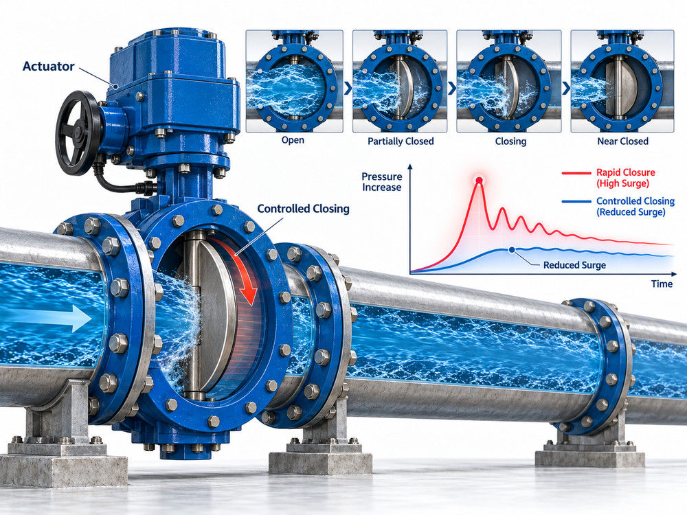
Worked Examples: DN800 Pump Discharge and Long Transmission Main
Example A: DN800 discharge butterfly valve after a pump trip
Consider a hypothetical DN800 pump-station discharge line with an electrically actuated isolation butterfly valve and a separate check valve. The pump loses power; flow decelerates while a programmed closure begins. If the check valve closes after substantial reverse velocity develops, its slam may generate a severe transient even when the butterfly valve takes 45 seconds to complete its stroke. The engineering response is to model actual pump coast-down and both valves’ dynamic characteristics, then coordinate the protection philosophy. Assigning the isolation valve a longer arbitrary stroke is not a validated fix.
Example B: A remote butterfly valve on a 2 km main
For a simplified 2,000 m hydraulic path and assumed wave speed of 1,000 m/s, the round-trip time is 4 seconds. A closure completed in 2 seconds warrants urgent surge screening; a 20-second closure may reduce the initial rapid-closure effect but still requires modelling of the network’s reflections and operating cases. If a designer changes the pipe material, the wave speed and pressure response can change as well. The lesson is to document assumptions before claiming a safe closing time.
Comparison: What Different Changes Actually Achieve
| Design action | Potential benefit | Important limitation |
|---|---|---|
| Increase overall closure time | May reduce the initial surge | Final movement may remain hydraulically rapid |
| Programme variable-speed closure | Shapes the rate of flow reduction | Requires valve characteristic and actuator capability |
| Coordinate pump and check valve | May limit reverse flow and slam | Must reflect failure and power-loss sequences |
| Add surge-protection equipment | May limit pressure extremes | Needs engineered sizing, location and maintenance |
| Use a higher pressure-rated valve | May improve valve pressure capacity | Does not protect weaker pipes, seals or supports |
Current Engineering Trend: From Valve Speed to System-Level Resilience
Modern water and desalination projects increasingly integrate variable-frequency drives, remote actuators, supervisory control and recorded pressure trends. These instruments make operational sequences easier to observe, but faster automation also creates opportunities for poorly coordinated commands. A practical procurement trend is therefore to ask suppliers for an actuator position-time curve, failure response, torque data and interface signals, rather than ordering by nominal diameter and voltage alone.
For seawater intake systems, corrosion-resistant wetted parts remain essential, but corrosion durability and surge resilience answer different questions. See the existing double-eccentric seawater butterfly-valve article for seat direction, materials and application details; this new guide avoids repeating those selections.
How to Specify a Butterfly Valve for a Surge-Sensitive Pipeline
A useful RFQ states the pipe diameter and profile, length, pipe material, flow range, static head, pump curves, anticipated trip sequences, minimum and maximum design pressures, required closing operation, emergency fail position and transient-study results if available. Also request manufacturer-specific Cv/Kv-versus-angle data, maximum differential-pressure capability, torque-versus-angle information, actuator output at minimum supply conditions and a proposed position-time curve.
Do not confuse a PN16 or Class 150 marking with proof of system surge suitability. Verify pressure-temperature ratings, short-duration loading rules under the applicable design code, gasket and flange capacities, pipe restraint, anchors and instrument connections. Pressure testing is not a substitute for a dynamic analysis.
For valve options and technical documentation, browse the Vcore butterfly valve product category or the flanged rubber-lined butterfly valve. Product selection remains conditional on the project’s measured operating and transient requirements.

Conclusion: Prevent the Pressure Event, Not Just the Noise
Effective water hammer prevention begins by treating the butterfly valve as one element of a dynamic network. Evaluate the velocity change, wave travel time, reflected pressure and the interaction of pumps, check valves and actuators. Then select a valve and actuation package that meets the demonstrated closing sequence and pressure envelope. If your team is planning a large-diameter pipeline or pump-station retrofit, contact Vcore Valve with the project datasheet and hydraulic analysis so the proposed valve configuration can be reviewed against the actual duty.
Frequently Asked Questions
Can a butterfly valve cause water hammer?
Yes. A butterfly valve can initiate a pressure transient when it changes flow velocity rapidly. The actual surge depends on the pipeline, valve flow characteristic, closing profile and operating conditions; the valve type alone does not determine the severity.
How slowly should a butterfly valve close to prevent water hammer?
There is no universal safe closing time. Compare the closure profile with the pipeline’s characteristic wave travel time, 2L/a, and verify the resulting maximum and minimum pressures through a transient analysis. A long overall stroke may still include a damaging rapid final movement.
Does an electric actuator prevent water hammer?
Not automatically. Electric actuation can provide adjustable speed and position feedback, but the configured speed, torque limits, control logic and failure behaviour must match the hydraulic study. A fast emergency command can still produce a severe transient.
What happens when a seawater intake pump trips?
Pump deceleration may cause falling pressure, flow reversal, pressure-wave reflection and possible column separation. Check valves, butterfly valves and surge-control devices must be coordinated according to the station’s pump-trip transient model.
Is PN16 sufficient for a pipeline with 10 bar operating pressure?
Not necessarily. Ten bar steady operating pressure does not establish the maximum transient pressure, minimum pressure, temperature-dependent allowable rating or loads on connected equipment. The full pressure envelope and applicable design code must be checked.
Can a check valve eliminate water hammer?
A correctly selected non-return valve can reduce damaging reverse-flow events, but it cannot eliminate all hydraulic transients. Check-valve slam itself may create a surge, so dynamic closing behaviour and pump-station layout require evaluation.
What information is required to specify a surge-conscious butterfly valve?
Provide the pipeline profile and length, internal diameters, pipe materials, fluid properties, operating flow, maximum and minimum pressures, pump curves and trip sequence, valve size and pressure rating, actuator type, closure profile, required fail position and any available transient-study results.