Electric ball valves are used in water treatment, chemical processing, oil and gas, HVAC, utility lines, manufacturing process lines, and industrial automation systems where remote operation, automated shutoff, or PLC integration is required. This guide explains how electric ball valves work, the main components, the difference between ON/OFF and modulating control, actuator torque selection, materials, applications, and the technical information buyers should prepare before requesting a quotation.
What Is an Electric Ball Valve?
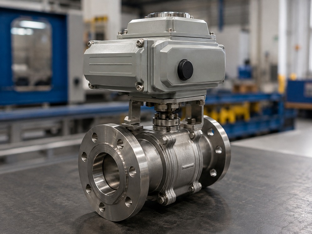
An electric ball valve is an automated valve assembly that combines a quarter-turn ball valve with an electric actuator. The ball valve provides the flow shutoff or routing function, while the electric actuator rotates the ball 90 degrees to open or close the pipeline. In a manual ball valve, an operator turns a handle or gear operator. In an electric ball valve, an electric motor drives the valve stem through a gear reduction system and coupling.
Electric ball valves are selected when remote operation, automated control, repeatable timing, or integration with a plant control system is required. They are common in processes where manual access is difficult, unsafe, or too slow, and where the valve must respond to signals from a PLC, timer, or remote control panel.
The actuator configuration varies by application. A small plastic valve may use a low-torque DC motor actuator, while a large flanged steel valve may require a high-torque multi-phase AC motor actuator with position feedback, manual override, and explosion-proof enclosure. Buyers should not assume that one actuator type suits all applications. For a broader overview of actuator mounting interfaces, see the valve actuator selection guide.
How Does an Electric Ball Valve Work?
An electric ball valve operates through the following sequence:
- Electric motor: The actuator contains an electric motor that converts electrical energy into rotational motion.
- Gear reduction: A gear train reduces the motor speed and increases the output torque to the level required by the valve.
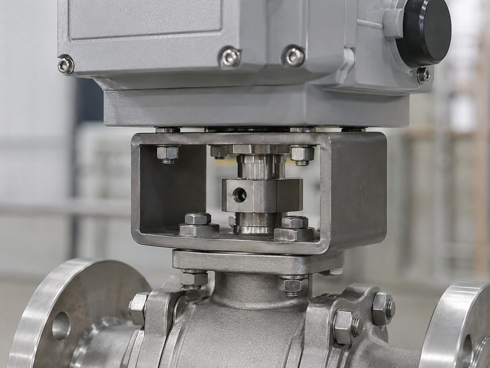
- Output shaft: The geared output shaft connects to the valve stem through a coupling and mounting bracket.
- Quarter-turn movement: The output shaft rotates approximately 90 degrees, turning the ball inside the valve body. When the ball bore aligns with the pipeline, the valve is open. When the solid side of the ball faces the flow, the valve is closed.
- Limit switches: Most actuators include mechanical or inductive limit switches that stop the motor at the fully open and fully closed positions.
- Position indication: A visual position indicator on the actuator housing shows whether the valve is open, closed, or in transition.
- Position feedback: Many actuators provide an electrical feedback signal (such as open/closed contact or analog position) so the control system can confirm valve status.
- Torque protection: Torque limiting or current limiting protects the actuator and valve stem if the valve encounters an obstruction or excessive resistance.
- Manual override: Most industrial electric actuators include a manual override (handwheel, lever, or clutch mechanism) that allows operation during power loss, commissioning, or maintenance.
Not every electric actuator contains all of these features. Buyers should confirm which features are included for a specific actuator model and whether they meet the application requirements.
Main Components of an Electric Ball Valve
An electric ball valve assembly includes the following main components:
| Component | Function | Selection Note |
|---|---|---|
| Valve body | Pressure-containing shell connected to the pipeline | Material must match pressure, temperature, and media compatibility |
| Ball | Rotating closure element with a bore for flow | Material must resist corrosion, wear, and erosion from the medium |
| Seats | Sealing interface between ball and body | PTFE, reinforced PTFE, metal, or other material depending on temperature and media. For extreme service, see valve materials for extreme temperature |
| Stem | Transmits rotational torque from actuator to ball | Must resist bending, torsion, and corrosion |
| Electric actuator | Drives the valve open and closed via electric motor | Sized by torque, voltage, duty cycle, control signal, and enclosure rating |
| Mounting bracket | Connects actuator to valve body | Must match ISO 5211 interface or valve-specific dimensions |
| Coupling | Transmits torque from actuator output shaft to valve stem | Must fit both shaft dimensions and handle the required torque |
| Limit switches | Stop motor at open and closed positions | Confirm type (mechanical, inductive, proximity) |
| Position indicator | Visual or electrical valve status | Verify if feedback signal matches control system requirements |
| Control module | Processes control signals and manages actuator operation | Must match voltage, control signal type, and communication protocol |
| Manual override | Allows manual operation without power | Confirm access is safe and practical for the installation |
ON/OFF vs Modulating Electric Ball Valves
Electric ball valves are used in two primary control modes: ON/OFF (also called open-close or two-position) and modulating (also called proportional or regulating). The control mode determines the actuator type, control signal, duty cycle, and valve design requirements.
ON/OFF Control
ON/OFF electric ball valves are the most common configuration. The actuator drives the valve to the fully open or fully closed position. This is suitable for isolation, batch transfer, tank filling and draining, utility line shutoff, and process sequencing where the valve does not need to hold an intermediate position.
ON/OFF actuators typically use simpler control circuits, lower duty cycle ratings, and standard limit switch arrangements. The valve seat design is optimized for tight shutoff rather than throttling wear resistance.
Modulating Control
Modulating electric ball valves are used when the valve must follow a control signal (such as 4-20 mA or 0-10 V) to hold an intermediate position for flow regulation. This requires an actuator designed for modulating duty, with higher duty cycle rating, position feedback, and a control module that accepts an analog input.
Buyers should not assume that a standard on/off ball valve is suitable for accurate throttling. A standard full-port ball valve is not designed to provide a predictable control characteristic across its full travel and may experience accelerated seat or ball wear under continuous throttling service.
V-Port Ball Valves for Throttling
Where modulating control is required with a ball valve, V-port ball valves or other control-oriented ball valve designs may be more appropriate. A V-port ball valve has a specially shaped ball bore that provides a more predictable flow characteristic across the travel range. Buyers should review the required flow characteristic, rangeability, seat wear risk, and actuator duty before selecting a ball valve for modulating service.
Electric Ball Valve Selection Guide
Selecting an electric ball valve requires matching the valve, actuator, and control system to the actual service conditions. The following factors should be reviewed before purchase.
Valve Size and Pressure Class
Valve size is determined by the pipeline size and flow requirement. The pressure class (PN rating or ASME class) must match or exceed the design pressure of the system. Buyers should confirm whether a full-port or reduced-port design is needed. Full-port ball valves use a bore designed to minimize flow restriction relative to the nominal pipeline size, providing lower pressure drop. Reduced-port valves have a smaller bore, which may be acceptable for isolation service but can affect flow capacity.
Body, Ball, Seat, and Seal Materials
Material selection depends on the process medium, temperature, pressure, and corrosion environment. Common body materials include carbon steel, stainless steel (304, 316, 316L), and ductile iron. Common seat materials include PTFE, reinforced PTFE (RPTFE), PEEK, nylon, and metal. The choice between soft seat and metal seat depends on temperature, abrasion risk, and fire-safe requirements. Seal materials include EPDM, FKM (Viton), NBR, and PTFE-based compounds.
No single material combination is suitable for all applications. Buyers should verify chemical compatibility, temperature limits, pressure limits, and regulatory requirements for the specific service condition. For detailed material comparison, review the valve material selection guide and the valve trim materials guide. For high-pressure forged body applications, see the forged valve materials guide.
Actuator Torque Selection
Actuator torque must exceed the valve breakaway torque and running torque under actual operating conditions. See the Electric Actuator Torque Selection section below for details.
Supply Voltage and Control Signal
Common actuator supply voltages include 24 V DC, 24 V AC, 110 V AC, 220 V AC, and 380 V AC (three-phase). The selected actuator must match the site power supply. Control signals for ON/OFF actuators are typically discrete (dry contact, voltage pulse, or relay). Modulating actuators accept analog signals such as 4-20 mA or 0-10 V. Buyers should confirm that the control signal type, wiring, and communication protocol match the plant control system.
Fail-Safe and Manual Override
Buyers should determine what the valve should do during power loss or control signal failure. A standard electric actuator without a fail-safe mechanism will remain in its last position when power is lost. To achieve automatic fail-close or fail-open behavior, a specific fail-safe design is required, such as:
- Spring-return electric actuator
- Battery backup or supercapacitor system
- Stored-energy mechanism
- Plant-level UPS or backup power system
Manual override is not the same as automatic fail-safe operation. A manual override allows an operator to move the valve by hand during power loss, but it does not cause the valve to move automatically to a safe position. Buyers should clearly specify whether automatic fail-safe action is required and confirm that the selected actuator design provides it.
Duty Cycle and Operating Frequency
Duty cycle indicates how long the actuator can operate within a given time period without overheating. Duty-cycle ratings vary significantly by actuator design and manufacturer. Modulating service generally requires an actuator specifically rated for more frequent starts, stops, and positioning duty than standard intermittent ON/OFF service. Buyers should confirm the expected operating frequency and select an actuator with adequate duty margin. For position verification in automated systems, see how to determine ball valve position.
Enclosure Protection and Hazardous Areas
The actuator enclosure must protect against the installation environment. Common IP ratings include IP65 (dust-tight, water jet), IP66 (dust-tight, powerful water jet), and IP67 (dust-tight, temporary immersion). For outdoor installation, direct sunlight, rain, or corrosive atmosphere, higher protection and appropriate materials may be required.
For hazardous locations, the actuator must have the appropriate approval or certification for the applicable area classification, such as ATEX or IECEx certification, or applicable UL/CSA hazardous-location approvals. Buyers should confirm the area classification and select an actuator with the matching protection concept (such as flameproof enclosure or intrinsic safety). For additional context on ball valve use in explosive atmospheres, see how ball valves work in hazardous locations.
Electric Actuator Torque Selection
Actuator torque selection is one of the most critical technical decisions in electric ball valve specification. Selecting an actuator by valve size alone is not reliable because different valve designs, seat materials, pressure ratings, and service conditions produce different torque requirements.
Breakaway Torque
Breakaway torque is the torque required to move the valve from the closed position. It is typically the highest torque the actuator must deliver because the seat has been pressing against the ball under full differential pressure, and static friction is higher than dynamic friction. Breakaway torque depends on:
- Valve size and design
- Seat material (PTFE, RPTFE, metal, nylon)
- Differential pressure across the ball
- Temperature (seat material friction changes with temperature)
- Duration of idle time (seats may cold-flow or adhere over time)
- Media cleanliness and deposits
Running Torque
Running torque is the torque required to keep the ball rotating after breakaway. It is typically lower than breakaway torque but must be sustained throughout the 90-degree travel. The actuator must also provide sufficient torque to seat the valve at the closed position (closing torque).
Factors Affecting Torque Over Time
Torque requirements can change over the service life of the valve. Factors that may increase torque include:
- Seat aging, compression set, or cold flow
- Deposit buildup on ball or seat surfaces
- Crystallization or scaling in the valve cavity
- Temperature changes affecting seat material properties
- Corrosion of stem or bearing surfaces
- Long idle periods causing seat adhesion
- Manufacturing tolerances between valve lots
Because of these variables, actuator selection should include a safety margin above the nominal valve breakaway torque. The appropriate margin depends on the application, seat material, and expected service conditions. Buyers should consult the valve manufacturer’s torque data and confirm the actuator output torque at the operating voltage and temperature. For broader automation guidance, review our article on automatic electric valves.
Materials and Media Compatibility
Material compatibility depends on the chemical, concentration, temperature, pressure, contaminants, and exposure conditions of the specific application. Buyers should verify compatibility for the actual service condition rather than relying on general resistance charts.
Common material combinations for electric ball valves include those summarized below:
| Service Condition | Common Body Material | Common Seat Material | Selection Note |
|---|---|---|---|
| Water and neutral fluids | Carbon steel, ductile iron, or stainless steel | PTFE or EPDM | Confirm pressure and temperature range |
| General chemical service | Stainless steel (316/316L) | PTFE or RPTFE | Verify concentration and temperature |
| Solvent service | Stainless steel or alloy | PTFE or compatible fluoropolymer | Review swelling and fire-safety requirements |
| High-temperature service | Stainless steel or alloy steel | Metal seat or high-temperature polymer | Review actuator heat isolation |
| Corrosive or hazardous media | Lined body, special alloy, or stainless steel | PTFE or compatible fluoropolymer | Confirm full material compatibility and certification |
For specific chemical plant applications, see our dedicated guide on electric ball valves in chemical plants.
Industrial Applications
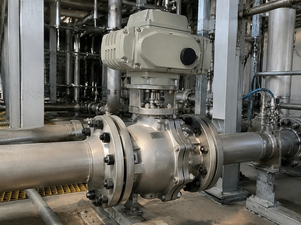
Electric ball valves are used across a range of industrial applications where automated flow control is needed:
- Water treatment: Automated isolation, filter backwash sequences, chemical dosing lines, and distribution control
- Chemical processing: Batch transfer, process sequencing, and remote isolation of corrosive or hazardous media. For chemical plant applications, see industrial valves for chemical processing
- HVAC: Chilled water isolation, hot water shutoff, and cooling system control
- Utility lines: Compressed air, cooling water, and general plant utility distribution
- Manufacturing process lines: Automated sequencing, filling, draining, and isolation
- Oil and gas: Pipeline isolation and process shutoff where the valve, actuator, electrical classification, and certification are suitable for the service
- Skid systems and packaged equipment: Pre-assembled valve packages with integrated control for rapid deployment
Each application has different requirements for material compatibility, pressure rating, actuator type, control signal, enclosure protection, and fail-safe behavior. Buyers should match the valve assembly to the actual operating conditions.
Electric Ball Valve vs Pneumatic Ball Valve
Electric and pneumatic actuators are the two most common automation methods for ball valves. The choice depends on site utilities, control requirements, actuation speed, fail-safe needs, and installation environment.
| Criterion | Electric Actuator | Pneumatic Actuator |
|---|---|---|
| Power source | Electrical supply (AC or DC) | Compressed instrument air |
| Actuation speed | Typically slower, depending on actuator size, gearing, and required torque | Typically faster, depending on actuator size, air pressure, accessories, and valve torque |
| Fail-safe option | Requires spring-return, battery backup, or stored-energy system | Spring-return configurations are widely available and can provide a straightforward mechanical fail-safe arrangement |
| Control signal | Direct electrical signal, easy PLC integration | Requires solenoid valve and air control accessories |
| Air supply | Not required | Requires clean, dry instrument air system |
| Installation environment | Needs electrical protection, enclosure rating | Needs air quality and freeze protection for air lines |
| Duty cycle | Check duty rating for frequent operation | Generally suitable for high-frequency cycling |
| Remote operation | Easy with cable or wireless signal | Requires air tubing or solenoid valve at location |
Neither technology is universally better. Electric actuators are practical where instrument air is not available, where wiring is easier than air tubing, or where integration with an electrical control system is the primary requirement. Pneumatic actuators are preferred where fast cycling is needed, where spring-return fail-safe is required without additional complexity, or where a reliable instrument air system is already available. For pneumatic actuator selection, review single vs double acting actuator differences. For pneumatic system planning, review pneumatic actuator air consumption. For a broader comparison, see our guide on manual and automatic valves selection.
Common Selection Mistakes
Many electric ball valve problems can be traced to selection errors made before the valve was purchased:
- Selecting actuator by valve size only: Torque depends on seat material, differential pressure, temperature, and valve design, not just nominal size.
- Ignoring breakaway torque: The actuator must overcome static friction at full differential pressure, which may be significantly higher than running torque.
- Ignoring differential pressure: A valve that is easy to open at low pressure may require much higher torque at full line pressure.
- Wrong voltage: Mismatched voltage between actuator and site power supply causes motor failure or insufficient torque.
- Wrong control signal: An ON/OFF actuator cannot accept a modulating signal, and vice versa.
- Ignoring duty cycle: Frequent cycling with a low-duty actuator causes motor overheating and premature failure.
- Ignoring ambient temperature: Extreme cold or heat affects actuator grease, motor performance, and enclosure seals.
- Wrong seat material: PTFE is not suitable for all media or temperature ranges. Metal seats may be needed for high temperature or abrasive service.
- Using a standard ball valve for unsuitable throttling duty: Standard full-port ball valves are designed for isolation, not precise flow regulation.
- Ignoring fail position requirements: Assuming the valve will fail closed without specifying a fail-safe actuator design.
- Ignoring enclosure protection: Outdoor or washdown environments require adequate IP rating and corrosion resistance.
- Ignoring hazardous-area requirements: Standard actuators are not suitable for explosive atmospheres without proper certification.
Electric Ball Valve RFQ Checklist
To request a quotation, buyers should provide the following information:
| Category | Required Information |
|---|---|
| Valve | Valve type, size, pressure class (PN or ASME), connection type (flanged, threaded, welded), full-port or reduced-port |
| Materials | Body material, ball material, stem material, seat material, seal material |
| Process conditions | Process medium, design pressure, operating pressure, design temperature, operating temperature |
| Actuator | ON/OFF or modulating, supply voltage, control signal type, position feedback requirement, fail-safe requirement, manual override requirement |
| Environment | Indoor or outdoor, ambient temperature range, enclosure rating, hazardous-area classification if applicable |
| Standards and certification | Applicable standards (API 608, ASME, ISO, EN), certificate requirements, inspection requirements |
| Project | Quantity, delivery requirement, special marking or packaging requirements |
FAQ
What is an electric ball valve?
An electric ball valve is an automated valve assembly that combines a quarter-turn ball valve with an electric actuator. The actuator uses an electric motor and gear reduction to rotate the ball 90 degrees, opening or closing the pipeline. Electric ball valves are used where remote operation, automated control, or integration with a plant control system is required.
How does an electric ball valve work?
An electric motor in the actuator drives a gear train that reduces speed and increases torque. The output shaft connects to the valve stem through a coupling and mounting bracket. When the actuator receives an electrical signal, the motor rotates the output shaft approximately 90 degrees, turning the ball inside the valve body to the open or closed position. Limit switches stop the motor at the end positions, and position feedback can be sent to the control system.
What is the difference between electric and pneumatic ball valves?
Electric ball valves use an electric motor actuator and require an electrical power supply. Pneumatic ball valves use compressed air and a pneumatic actuator. Electric actuators are practical where instrument air is not available and are easy to integrate with electrical control systems. Pneumatic actuators are typically faster, simpler for spring-return fail-safe operation, and suitable for high-frequency cycling where a reliable air supply exists.
Can an electric ball valve be used for flow control?
A standard ball valve is primarily an isolation valve and is strongest in fully open or fully closed service. When fitted with a modulating actuator, an electric ball valve can provide limited position control, but the flow characteristic of a standard full-port ball valve is not ideal for precise throttling. For applications requiring accurate flow regulation, a V-port ball valve, control valve, or other valve type designed for modulating duty should be considered.
How do I size an electric actuator for a ball valve?
Actuator sizing should be based on the valve breakaway torque, running torque, and closing torque under actual operating conditions. Torque depends on valve size, seat material, differential pressure, temperature, and media. Buyers should obtain the valve torque data from the manufacturer, apply an appropriate safety margin for seat aging and operating conditions, and confirm that the actuator output torque meets or exceeds the required value at the operating voltage and temperature.
Can an electric ball valve fail closed during power loss?
A standard electric actuator will remain in its last position when power is lost. It will not automatically move to a closed or open position unless a specific fail-safe design is used. Fail-safe operation requires a spring-return actuator, battery backup system, supercapacitor module, or another stored-energy arrangement. Buyers should specify whether automatic fail-safe action is required and confirm that the selected actuator design provides it. A manual override is not a substitute for automatic fail-safe operation.
What information is required to order an electric ball valve?
Buyers should provide valve type, size, pressure class, connection type, body and trim materials, seat and seal materials, process medium, design and operating pressure, design and operating temperature, supply voltage, control signal type (ON/OFF or modulating), position feedback requirement, fail-safe requirement, manual override requirement, enclosure rating, hazardous-area classification if applicable, applicable standards, certificate requirements, inspection requirements, and quantity.
Request a Quotation
Vcore Valve can review your technical requirements and recommend a suitable electric ball valve package for your application. To request a quotation, provide the valve type, size, pressure class, materials, process medium, temperature, pressure, supply voltage, control signal, fail-safe requirement, and required standards. Contact Vcore Valve with your project specifications.