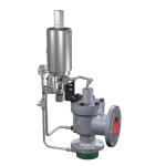
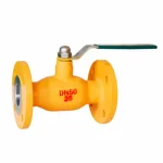
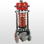
Boiler blowdown valve selection should distinguish TDS/surface blowdown from bottom blowdown. TDS blowdown removes concentrated boiler water to control dissolved solids and may operate continuously or intermittently under conductivity control. Bottom blowdown removes precipitated solids from low points of the boiler and is normally an intermittent discharge duty. These services create different valve requirements. Selection should consider boiler pressure and temperature, upstream and downstream pressure, flashing risk, solids content, operating frequency, required flow control, trim erosion, shut-off duty, actuator method, discharge piping and the approved boiler operating procedure.
Power & Steam · Boiler Water Management Duty Sheet
Boiler Blowdown Valve Selection: TDS/Surface vs Bottom Blowdown
“Boiler blowdown” describes more than one service. Surface/TDS blowdown controls dissolved solids in boiler water, while bottom blowdown removes settled solids from the boiler low point. A valve selected only by pipe size or the word “blowdown” can therefore be wrong for the actual duty.
Two Blowdown Duties — Two Different Selection Problems
SURFACE / TDS BLOWDOWN
Control Dissolved Solids
Water is removed from a region representative of boiler-water concentration so the TDS or conductivity level can be controlled. Depending on the control system, the valve may operate continuously, modulate, or open intermittently for sampling and discharge.
- Clean or relatively low-solids hot boiler water
- Stable flow control or repeatable opening
- High pressure drop and flashing review
- Automatic conductivity-control compatibility where required
BOTTOM BLOWDOWN
Remove Settled Solids
Water and precipitated solids are discharged from boiler low points. The duty is normally intermittent and can be highly erosive because hot pressurized water, flashing steam and solids pass through the valve and downstream piping.
- Intermittent discharge
- Possible sludge, scale or sediment
- Seat and trim erosion risk
- Operator safety and discharge-system review
Terminology note: “intermittent blowdown” can be ambiguous. A TDS control system can also use intermittent valve opening. For valve selection, identify whether the duty is TDS/surface blowdown or bottom blowdown, then state the actual operating sequence.
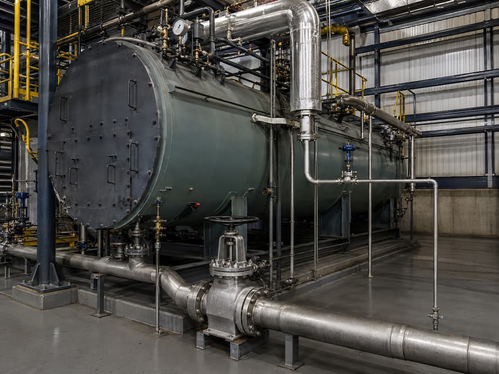
Why Blowdown Service Can Be Severe
Hot pressurized water
Large pressure drop
Solids
Repeated cycling
The downstream blowdown vessel, flash vessel, separator or drain system is part of the pressure-release path. Valve selection should therefore use both upstream and downstream conditions rather than boiler pressure alone.
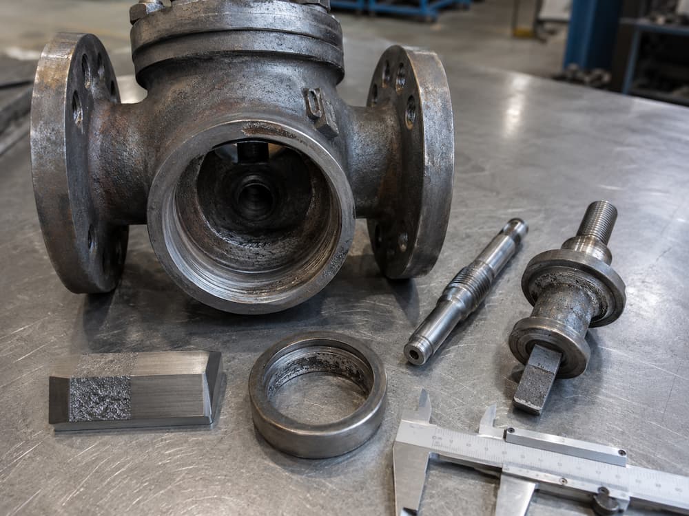
DUTY A
TDS / Surface Blowdown Valve Selection
A TDS blowdown valve is part of the boiler-water concentration-control system. The required valve behavior depends on how conductivity is measured and how the controller operates the discharge valve.
| Control Mode | Valve Requirement | Key Risk |
|---|---|---|
| Continuous / modulating discharge | Stable repeatable flow control at the required small-to-normal blowdown rate. | Seat erosion, excessive flow at small travel, poor control range. |
| Intermittent TDS sampling / discharge | Reliable repeatable opening and closing with the approved conductivity-control sequence. | Unstable sampling, excessive discharge or poor shut-off after cycling. |
Selection inputs
- Boiler operating and design pressure
- Boiler-water temperature
- Required blowdown flow or controller sizing basis
- Downstream pressure / blowdown vessel condition
- Continuous, modulating or intermittent control sequence
- Required actuator and fail position
- Seat / trim material and erosion requirement
A dedicated TDS blowdown control valve may be preferable where automatic flow control is required. Do not assume a general shut-off globe valve will provide stable low-flow control under a large boiler pressure drop.
DUTY B
Bottom Blowdown Valve Selection
Bottom blowdown removes settled solids from low points in the boiler. The valve should therefore be reviewed as an intermittent hot-water, flashing and potentially solids-bearing discharge service rather than as an ordinary drain.
Valve-side review
- Full opening capability for solids discharge
- Seat and trim erosion resistance
- Geometry that does not unnecessarily trap solids
- Reliable shut-off after blowdown
- Manual or automated operating method
- Cycle frequency and expected blowdown duration
System-side review
- Boiler low-point connection
- Downstream vessel / receiver pressure
- Pipe support under flashing discharge
- Safe operator position
- Drain and vent routing
- Plant and boiler OEM operating procedure
Some boiler installations use two valves in series for bottom blowdown. The exact valve types, operating sequence and which valve is intended to absorb throttling wear must follow the boiler manufacturer, site procedure and selected valve IOM. It should not be generalized into one universal opening/closing sequence.
Valve Type Decision Matrix
| Valve / Design | Where It May Fit | Main Limitation |
|---|---|---|
| Dedicated TDS blowdown control valve | Automatic TDS / conductivity-control duty requiring repeatable flow control. | Must be sized from actual blowdown flow and pressure drop. |
| Throttle / emptying stop valve | Controlled drainage or blowdown after service review. | Not every configuration is suitable for severe continuous throttling. |
| High-pressure globe / angle globe valve | Selected shut-off or throttling duties where pressure-temperature and trim are confirmed. | Generic globe geometry does not automatically solve flashing erosion. |
| Quick-opening / rotary blowdown valve | Selected bottom-blowdown systems where rapid full opening is part of the approved design. | Do not use as a generic throttling rule; follow OEM sequence and system design. |
Vcore’s existing Throttle Emptying Stop Valve is already positioned for controlled drainage and blowdown service after project review. For higher-pressure steam and boiler service, the Globe Valve category also includes pressure-seal and high-pressure globe-valve options.
Flashing vs Cavitation in Blowdown Service
These two mechanisms should not be treated as synonyms.
| Mechanism | What Happens | Blowdown Relevance |
|---|---|---|
| Cavitation | Local pressure falls below vapor pressure, vapor forms, then collapses when pressure recovers. | Can damage liquid-service valve trim where downstream pressure recovers sufficiently. |
| Flashing | Liquid pressure falls below the saturation condition and part of the liquid remains vapor downstream. | Common concern when hot boiler water is discharged to a much lower-pressure blowdown system. |
A trim material that survives ordinary water throttling may still wear quickly in sustained two-phase flashing service. Downstream pipe velocity and impingement areas should be reviewed together with the valve.
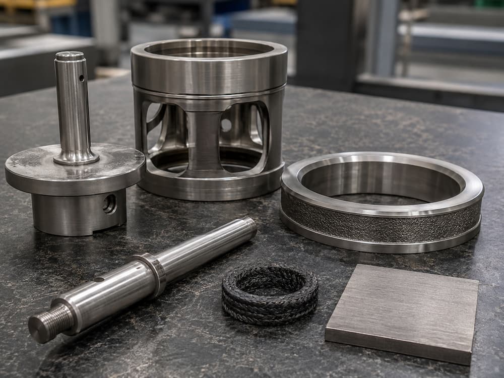
Materials, Seat and Bonnet Review
Body material
Select from the actual boiler-water pressure-temperature condition and project material specification. Carbon steel or alloy steel may be required depending on service.
Seat / trim
Hardfacing or hardened trim may be considered where flashing, solids or repeated cycling creates erosion risk. The exact material should follow the selected design.
Bonnet / pressure boundary
Bolted, welded or pressure-seal construction should be selected from pressure, temperature, size and approved project specification rather than from service name alone.
Packing / gasket
High-temperature graphite or another qualified sealing system may be required. The complete pressure-temperature rating must include body, bolting, gasket and packing limits.
For pressure-temperature selection, see the Valve Pressure-Temperature Rating Guide and High Temperature High Pressure Valves Guide.
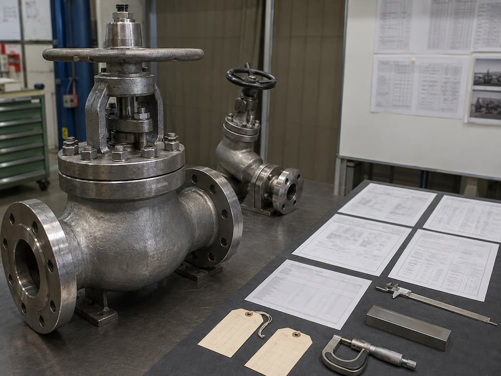
Common Selection Errors
State whether the function is TDS/surface control or bottom-solids removal.
Downstream pressure determines the actual valve pressure drop and flashing severity.
Trim geometry, seat material and operating frequency matter.
Sludge and scale can change both erosion behavior and required valve opening.
Use the boiler OEM, valve IOM and site operating procedure for the selected arrangement.
Boiler Blowdown Valve RFQ Data
Service Identification
- TDS / surface blowdown or bottom blowdown
- Continuous, modulating, timed or manual operation
- Boiler type / service description
- Expected solids condition
Pressure & Temperature
- Boiler operating pressure
- Design pressure
- Boiler-water temperature
- Downstream / blowdown vessel pressure
Flow & Operation
- Required blowdown flow if known
- Cycle frequency
- Typical discharge duration
- Required valve opening behavior
- Manual / pneumatic / electric operation
Valve & Project Data
- Size and end connection
- Body / trim material requirement
- Leakage / shut-off requirement
- Testing and NDE
- Material certificates / inspection documents
- Applicable boiler / EPC specification
Inspection and Verification
| Check | Purpose |
|---|---|
| Material verification | Confirm body, trim and specified pressure-containing materials. |
| Shell / pressure test | Verify pressure-boundary integrity to the applicable purchase specification. |
| Seat leakage test | Confirm shut-off performance where specified. |
| Trim / seat inspection | Confirm hardened or special blowdown trim when ordered. |
| Actuation / cycling check | Verify travel and fail behavior for automated blowdown valves. |
| Final end protection | Protect machined or welded ends before shipment. |
Related Technical Resources
Technical References
Frequently Asked Questions
What is the difference between surface blowdown and bottom blowdown?
Surface or TDS blowdown removes concentrated boiler water to control dissolved solids. Bottom blowdown removes precipitated solids and sludge from boiler low points. The two duties can require different valve designs and operating methods.
Is boiler blowdown always continuous?
No. TDS blowdown may be continuous, modulating or intermittently operated depending on the control system. Bottom blowdown is normally an intermittent discharge duty.
Why can boiler blowdown valves erode quickly?
Hot pressurized boiler water can undergo a large pressure drop through the valve. Flashing, high velocity, solids and repeated cycling can concentrate wear on the seat, trim and downstream piping.
Can a standard globe valve be used for boiler blowdown?
Only after the actual duty is reviewed. A general globe valve may not be suitable for severe flashing, high-frequency cycling or solids-bearing bottom blowdown. Pressure drop, trim geometry, seat material and shut-off requirement should be checked first.
Do bottom blowdown systems always require two valves?
No universal arrangement should be assumed. Some systems use two valves in series, but the required configuration and operating sequence must follow the boiler manufacturer, project specification, valve IOM and site operating procedure.
What information is needed to quote a boiler blowdown valve?
Provide whether the duty is TDS/surface or bottom blowdown, boiler operating and design pressure, water temperature, downstream pressure, required flow if known, solids condition, operating frequency, valve size, connection, materials, actuation and project testing requirements.