PTFE lined valves for vacuum service must be selected by the complete valve design, minimum absolute pressure, temperature during vacuum exposure, chemical composition and operating cycle. Chemical resistance and a positive-pressure rating do not establish vacuum suitability. Before ordering, obtain model- and size-specific confirmation of lining support, sealing performance and the applicable vacuum–temperature operating envelope.
Selecting PTFE lined valves for vacuum service requires more than matching a lining material to a corrosive chemical. The valve must also withstand the specified pressure differential, remain mechanically stable and provide the required sealing performance throughout the operating cycle.
Vacuum may occur during solvent recovery, reduced-pressure processing or vessel evacuation. It may also develop during shutdown when vapor condenses inside an isolated section. A valve therefore needs to be reviewed for normal operation, cleaning, startup and shutdown conditions.
This guide explains the differences between chemical resistance and vacuum suitability, the role of lining support, the importance of absolute pressure, and the inspection information buyers should obtain before ordering.
For a broader application framework, read our Industrial Valves for Chemical Processing guide. For a comparison of closure and sealing structures, see PTFE Lined Diaphragm Valve vs Plug Valve for Corrosive Chemical Service.
1. PTFE Lined Valves for Vacuum Service: Key Selection Factors
A chemical-compatible lining, a metal body’s positive-pressure rating and a complete valve’s vacuum performance answer different engineering questions. The procurement specification should address each one separately.
| Selection Factor | What It Establishes | What Still Requires Verification |
|---|---|---|
| Chemical compatibility | Suitability of specified wetted materials for the actual medium. | Liner stability, leakage and operation under vacuum. |
| Positive-pressure rating | Approved pressure duty under stated temperature and configuration limits. | Minimum absolute pressure and complete assembly behavior. |
| Liner retention | How the lining is supported or retained in the offered construction. | Evidence covering valve size, temperature and exposure duration. |
| Vacuum sealing | Specified air-ingress or seat-leakage performance. | Test method, direction, temperature and acceptance criteria. |
| Operating cycle | Required pressure/temperature transitions and actuation duty. | Approval for the complete sequence, including cleaning and shutdown. |
2. Absolute Pressure: Define the Vacuum Duty Before Comparing Valves
Terms such as “high vacuum,” “90% vacuum” and “full vacuum” are insufficient on their own. State the minimum internal absolute pressure at the valve, the external pressure and the temperature that occurs at the same time. Also identify which side of a closed valve is evacuated.
Absolute pressure = gauge pressure + local atmospheric pressure.
At an assumed atmospheric pressure of 1.013 bar(a), a reading of −0.90 bar(g) corresponds to 0.113 bar(a), or 113 mbar(a). This is an illustrative conversion, not a valve rating.
Lower absolute pressure means deeper vacuum. A valve operated at 50 mbar(a) experiences a deeper vacuum than one operated at 300 mbar(a). Do not compare quotations until their pressure units and reference conditions match.
| RFQ wording | What is missing | Better specification |
|---|---|---|
| Vacuum suitable | Pressure, temperature, duration and valve condition | Minimum ___ mbar(a) at ___ °C for ___ hours; valve open/closed |
| −0.09 MPa | Gauge or absolute reference; atmospheric basis if gauge | State gauge reference and corresponding absolute pressure |
| Full vacuum | Defined minimum absolute pressure and temperature | Specify the required absolute pressure and test/operating limits |
| PN16 or Class 150 | Vacuum capability of the complete lined assembly | Add the applicable vacuum–temperature envelope for the offered size and design |
3. Lining Support: Why Corrosion Resistance Does Not Prove Vacuum Resistance
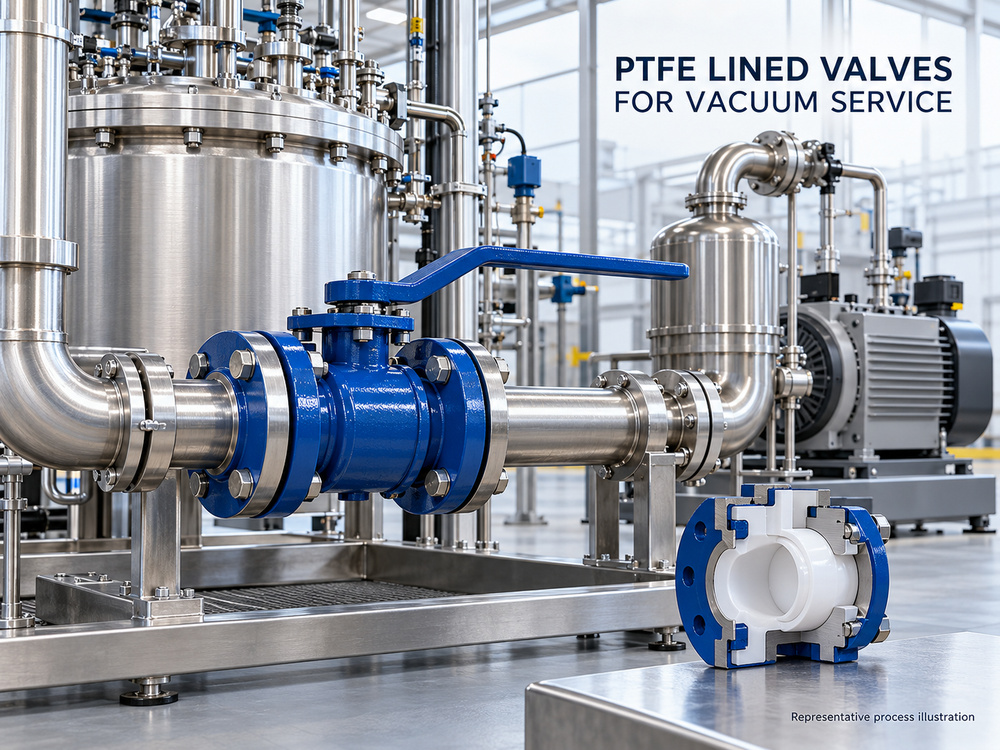
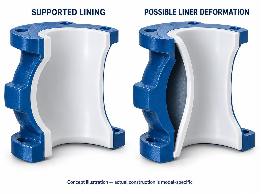
The metal housing and the fluoropolymer lining perform different functions. Under vacuum, pressure behind a liner can exceed process pressure and load the liner inward. Inadequate support can allow deformation that obstructs the flow passage or interferes with moving parts. The relevant limit belongs to the assembled design, not to the polymer name alone.[1]
Ask the supplier to identify the actual lining material and construction. A commercial “PTFE lined” product family may offer different fluoropolymers; the quotation should specify the material supplied for each wetted component. Do not treat PTFE, PFA and FEP as interchangeable descriptions.
What the construction review should establish
- The lining retention or support arrangement in the body and closure member.
- The sizes, temperatures and vacuum conditions covered by the manufacturer’s evidence.
- The treatment of body cavities and any manufacturer-provided vent or monitoring features.
- The complete wetted-material schedule, including seats, seals, diaphragm and exposed metallic parts where applicable.
Some lined designs use mechanical anchoring to retain the liner. That is a design feature requiring verification, not evidence that every lined valve has the same capability.[2] For chemical compatibility beyond the liner, review corrosion-resistant valves for acid and alkali pipelines.
4. Chemical Compatibility: Concentration, Permeation and Cleaning Media
Chemical compatibility should be checked for the actual concentration and temperature, including impurities and cleaning fluids. A compatibility statement for one pure chemical does not resolve a mixed-solvent or changing-concentration duty.
Permeation through a polymer is different from an open leak path. Depending on service conditions, permeated material may accumulate behind a liner and affect its loading. Where a design includes vent or monitoring passages, follow its instructions; do not seal such features with paint, insulation or plugs without manufacturer approval. Suspected process leakage requires investigation under the site’s isolation procedure.[4]
For flammable media, include the project’s electrostatic-control and area-classification requirements in the enquiry. Standard fluoropolymer lining should not be assumed to provide a qualified conductive path. Ask for evidence for the proposed assembly rather than relying on a generic “anti-static” statement.
5. Valve Structure: Ball, Plug, Butterfly and Diaphragm Options
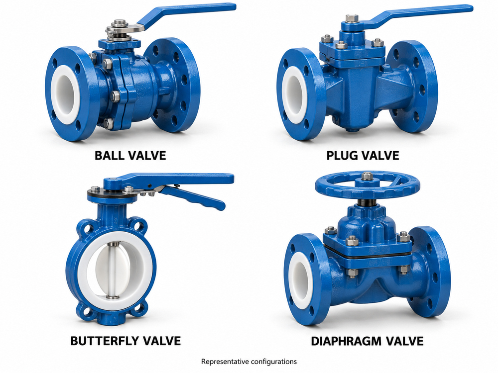
Valve selection starts with the required function: isolation, selected flow adjustment or automated sequencing. The following table identifies review questions; it does not rank these valve types by vacuum capability. Each offered model needs its own confirmation.
| Valve design | Potential project role | Vacuum-specific buyer checks |
|---|---|---|
| PTFE lined ball valve | Quarter-turn chemical isolation | Body/ball lining, seat directionality, cavity arrangement, stem sealing and torque under the specified duty |
| PTFE lined plug valve | Quarter-turn isolation in a compatible process | Plug/body lining support, seal arrangement, operating torque and size-specific vacuum limits |
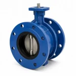
| PTFE lined butterfly valve | Compact isolation where the selected design is suitable | Liner retention, disc coating, shaft sealing, pressure direction and adjacent lined-pipe clearance |
| PTFE lined diaphragm valve | Isolation or permitted flow adjustment | Body lining plus diaphragm construction, attachment, backing arrangement, pressure differential and cycle limits |
6. Temperature and Operating Cycles: Check the Complete Vacuum Envelope
Do not combine a maximum-temperature statement from one document with a vacuum statement from another. Request the approved pressure/vacuum–temperature diagram or written operating envelope for the exact valve series, size, lining and seal configuration. Manufacturer literature for lined ball valves explicitly directs selection to the relevant vacuum–temperature conditions.[3]
Build the review around the actual operating sequence. A room-temperature evacuation, a hot vacuum hold and a cool-down after cleaning are separate conditions. Where maximum temperature and deepest vacuum never coincide, provide the actual combinations rather than leaving the supplier to assume them.
| Operating stage | Data to provide | Question for the supplier |
|---|---|---|
| Evacuation | Starting temperature, final absolute pressure, evacuation time | Does the approved envelope cover the transition? |
| Normal vacuum hold | Pressure, temperature and hold duration | Is the offered configuration suitable for continuous or stated intermittent duty? |
| Hot cleaning and cool-down | Cleaning medium, maximum temperature and pressure history | Are thermal transitions and possible condensation-induced vacuum covered? |
| Return to pressure | Repressurization sequence and maximum positive pressure | Are both ends of the operating cycle covered? |
| Abnormal condition | Credible minimum pressure and simultaneous temperature | What protection or operating restriction is required? |
7. Sealing and Testing: Liner Stability, Air Ingress and Seat Leakage
A mechanically stable liner is only one acceptance item. The assembly may also need to limit air entering through external joints and leakage across the closed valve. These are different paths and should have separate acceptance criteria.
| Requirement | What it evaluates | What to define |
|---|---|---|
| Lining stability | Ability of the supported lining to withstand the specified exposure | Absolute pressure, temperature, duration, valve position and inspection criteria |
| External leak tightness | Air ingress from outside through seals and joints | Method, test configuration, gas, pressure, temperature and allowable leak rate |
| Seat tightness | Leakage from one side of a closed valve to the other | Pressure on both sides, direction, medium and acceptance limit |
| Functional operation | Travel, torque or thrust and repeatability | Operating differential pressure, supply conditions, cycle count and pass/fail criteria |
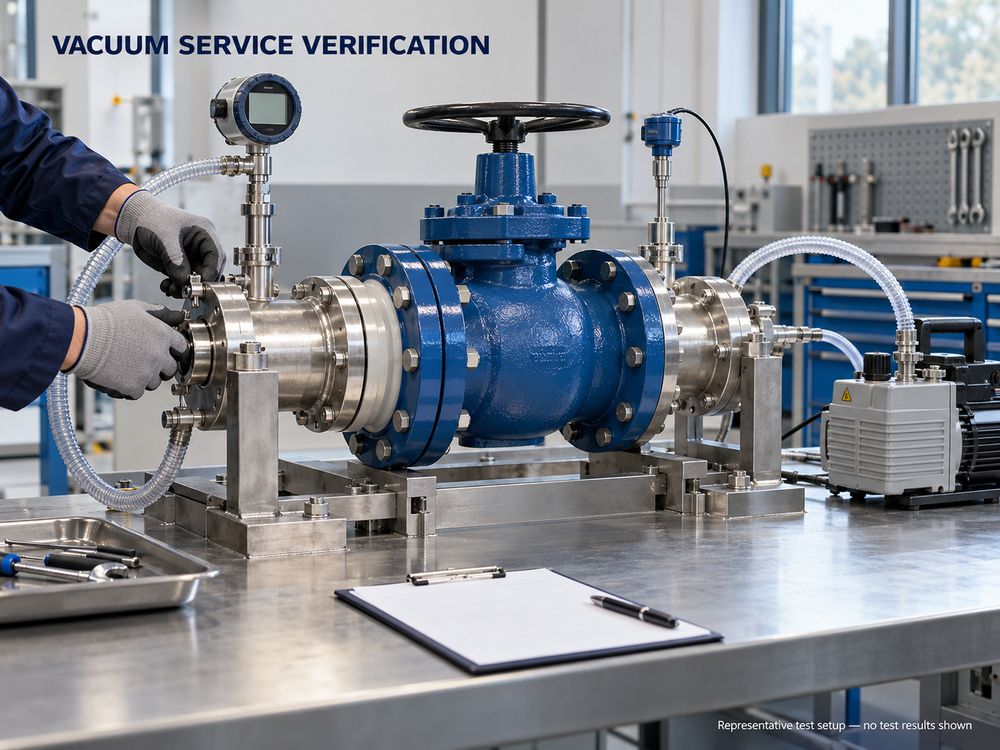
A positive-pressure shell test alone cannot establish all of these requirements. Similarly, a room-temperature vacuum hold is not evidence of performance at an unspecified elevated temperature. Test records should state exactly what was tested and what remained outside scope.
Where a pressure-rise method is proposed, the procedure should account for test volume, stabilization, temperature effects and background gas release. Where a tracer-gas method is required, agree the method and units explicitly. “No visible leakage” is not an adequate substitute for a specified vacuum leak-rate criterion.
Use the project’s inspection and test plan when that document is available, or agree a dedicated inspection schedule. A useful submission package should answer the following questions:
- Configuration: Does the datasheet identify valve model, size, body, lining, seals, ends and operator?
- Operating envelope: Is the stated minimum absolute pressure approved at each relevant temperature?
- Evidence applicability: Does qualification cover the offered configuration, or is additional project testing required?
- Test conditions: Are pressure reference, temperature, duration, medium, direction and valve position recorded?
- Acceptance: Are lining condition, leakage and functional criteria agreed before testing?
- Traceability: Can the report be linked to the tested valve or qualification sample?
- Restrictions: Are operating limits, installation instructions and maintenance requirements supplied?
Keep design-qualification evidence separate from routine production inspection. A witnessed valve factory acceptance test should verify the scope agreed for the order; it should not be described as hot-vacuum qualification unless that work was actually specified and performed.
8. Installation and Maintenance: Preserve the Approved Valve Configuration
Protect lined sealing faces during handling, align the mating flanges and support the piping before tightening. Follow the supplied instructions for gaskets, bolt sequence, torque and any recheck after commissioning. Do not transfer torque values from an unrelated unlined valve.[4]
For butterfly valves, confirm that the disc clears the adjacent lined component through the permitted travel.[1] Check access to the operator, position indication and any inspection points before final installation.
If the system can exceed the approved vacuum envelope, the process designer should define the required protection. A vacuum-breaking arrangement is not an automatic solution: the admitted fluid, contamination risk and process safety requirements must also be reviewed.
Maintenance and Replacement Planning
Maintenance costs should be assessed against the service cycle and the selected construction. Ask which seals, diaphragms or lining-related components can be replaced, what inspection is required after repair and whether the original vacuum qualification still applies to the repaired configuration.
Record operating torque or thrust, stroke behavior and observed leakage using the approved maintenance procedure. A change in performance should trigger investigation of the process conditions and valve condition rather than simply increasing actuator force.
| Maintenance Item | Buyer Review |
|---|---|
| Replacement seals or diaphragm | Correct material, traceability, availability and manufacturer-approved fitting procedure. |
| Lining inspection | Inspection method and acceptance criteria for damage, distortion or other service-related deterioration. |
| Post-repair verification | Required leakage, operation and vacuum checks before returning the valve to service. |
| Downtime planning | Access, isolation requirements, spare parts and specialist repair support. |
9. Application-Based Review: A Heated Solvent-Recovery Example
Example only—not a Vcore delivery case or a product rating. An enquiry describes a DN50 lined isolation valve operating at 150 mbar(a) and 80 °C, with a two-hour vacuum hold and six evacuation cycles per day. The system also has a separate positive-pressure transfer stage.
A useful technical response would first request solvent composition, cleaning conditions, the positive-pressure stage, shut-off direction and the lowest pressure during upset or cool-down. It would then identify an offered configuration and the evidence covering those conditions. A generic ambient “full vacuum” statement would leave the hot hold unresolved.
The commercial comparison should show whether each supplier includes the same lining, seal package, qualification basis, project tests and documentation. Compare price after resolving those differences.
10. Procurement Checklist Before Requesting a Quotation
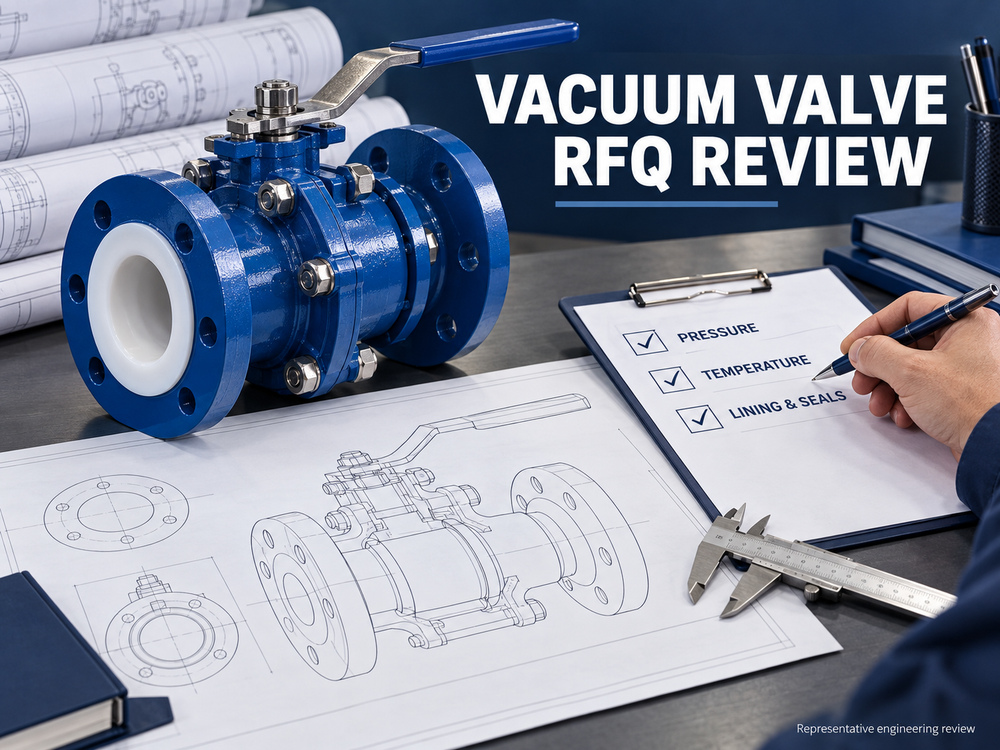
Use this checklist to turn a general vacuum enquiry into a reviewable valve specification. Enter actual values or mark an item “to be confirmed”; do not substitute a nominal pressure class for missing vacuum data.
| RFQ item | Information to provide |
|---|---|
| Identification | Project/tag; quantity; valve function; preferred valve type |
| Size and ends | DN/NPS; flange standard/rating; face-to-face and mating component details |
| Process chemistry | Medium, concentration, phase, impurities, solids and cleaning fluids |
| Vacuum exposure | Minimum and normal absolute pressure; external pressure; pressure on each side when closed |
| Temperature and timing | Simultaneous temperatures; duration; cycle frequency; transition and upset conditions |
| Positive pressure | Operating/design pressure and temperature for other stages |
| Materials | Required lining, seats, diaphragm/backing if applicable, seals and exposed metals |
| Operation | Manual/pneumatic/electric; fail action; supply; opening/closing time; cycling |
| Acceptance and documents | Vacuum envelope; leakage criteria; qualification and production-test scope; GA; inspection records |
11. Explore Vcore Valve’s PTFE Lined Chemical Valve Options
Vcore Valve’s lined chemical valve range provides several structures to consider during project review. The linked product pages describe product families; a particular vacuum duty requires written confirmation for the offered configuration.
PTFE Lined Ball Valve for Chemical Service
A quarter-turn isolation option for selected corrosive chemical transfer and process duties.
Key selection points:
Body and ball lining, seats, cavity arrangement, stem seals, operating torque and vacuum–temperature limits.
PTFE Lined Plug Valve for Chemical Service
A compact quarter-turn option where the selected plug and lining configuration suits the process.
Key selection points:
Plug construction, lining retention, stem sealing, port geometry and breakaway torque.
PTFE Lined Butterfly Valve for Chemical Service
A compact isolation option where the proposed disc, liner and shaft-seal arrangement meets the project requirements.
Key selection points:
Liner retention, pressure direction, disc clearance, shaft seals and model-specific vacuum evidence.
PTFE Lined Diaphragm Valve for Chemical Service
An option for selected chemical duties requiring separation of the operating mechanism from the process medium.
Key selection points:
Body lining, diaphragm attachment and backing, differential pressure, cycling and the approved operating envelope.
12. Final Selection Considerations
The selection of PTFE lined valves for vacuum service should begin with the minimum absolute pressure, the temperature occurring at the same time and the full process cycle.
Review the complete wetted-material system, liner support, valve geometry, sealing direction and operating requirements. A material compatibility statement or a positive-pressure designation alone cannot resolve those questions.
Before accepting the technical offer, align the approved datasheet, drawing, operating envelope, test scope and installation instructions. For related failure mechanisms, read Common Valve Failures in Chemical Pipelines. For alternative lining systems, see PTFE Lined Valve vs Rubber Lined Valve.
Frequently Asked Questions
1. Can all PTFE lined valves be used under vacuum?
No. Suitability depends on the complete valve construction and its approved operating envelope. Verify the exact size, lining, seals, pressure and temperature rather than relying on the material name.
2. Does PN16 mean the valve can withstand full vacuum?
No. A positive-pressure designation does not establish the liner’s vacuum capability or the assembly’s inward-leakage performance. State the minimum absolute pressure and request separate confirmation.
3. Is PFA always better than PTFE for vacuum service?
No universal ranking applies. The manufacturing method, liner support, geometry, chemical duty and verified operating limits matter. Compare complete offered designs.
4. Which pressure unit should I use in a vacuum valve RFQ?
Use an explicitly absolute unit, such as mbar(a), kPa(a) or bar(a). If providing gauge vacuum as well, identify the atmospheric reference used for conversion.
5. Can a standard pressure test replace a vacuum test?
Not by itself. The test must address the required lining stability, air ingress, seat leakage and operation under the specified conditions. Define project verification separately from routine pressure testing.
6. Should I choose a ball, plug, butterfly or diaphragm valve?
Choose by function, chemistry, size, flow requirements and operation, then verify the selected configuration for vacuum. No valve type is automatically suitable solely because it has fluoropolymer lining.
Technical References
These sources explain general lining principles and examples of manufacturer-specific construction. They do not certify Vcore products or transfer another manufacturer’s ratings to an offered valve.
- CRP — Introduction to PTFE/PFA Lined Piping: lining support, vacuum behavior and adjoining lined-component considerations.
- CRP — Atomac Lined Valve Construction: an example of mechanical liner anchoring.
- Atomac AKH2 Technical Data: product-specific reference to pressure/vacuum–temperature conditions.
- CRP Lined Piping User Manual: handling, vent features, permeation and installation principles; the supplied valve’s instructions remain controlling.
Need a PTFE Lined Valve for Your Chemical Vacuum Service?
Share your process conditions with Vcore Valve so the required lined-valve configuration, sealing system and documentation can be reviewed before quotation.
For quotation, please provide:
Valve size and quantity, chemical medium and concentration, minimum absolute pressure, simultaneous operating temperature, vacuum duration, cycling frequency, positive-pressure conditions, end connections, operation method and test requirements.