Check Valve Selection for Variable-Speed Pumps: Minimum Flow and Disc Stability
A variable-frequency drive allows a pump to respond to changing demand. The discharge check valve must operate across that changing hydraulic range. A valve that behaves well at peak duty may spend hours at reduced opening during overnight demand, seasonal operation or multi-pump staging.
This guide focuses on sustained low-flow operation and the information buyers need to evaluate it. For the broader arrangement and backflow function, start with our check valves for pump discharge guide.
1. Why Variable Speed Changes the Selection Task
Lower pump speed changes the pump curve, but it does not guarantee that flow falls in direct proportion to speed in the installed system. Static head, downstream pressure and friction losses determine the new operating point. The Hydraulic Institute explains this interaction in its pump and system operating-point guidance.
Use calculated or measured flow at each intended operating condition. A statement such as “30–50 Hz operation” does not provide enough information to size a check valve. The same speed range can produce very different discharge flows in different systems.
Also record how long each condition lasts. A brief startup transition and six hours of low-demand operation deserve different evaluations, even if both pass through the same flow value.
2. Separate Three Different Low-Flow Requirements
| Term | What it describes | Who should confirm it? |
|---|---|---|
| Pump minimum permitted flow | The operating limit needed to protect the pump for the relevant speed and duty | Pump manufacturer and system designer |
| Check-valve cracking pressure | The differential pressure at which opening begins under stated conditions | Valve manufacturer for the exact orientation and configuration |
| Minimum stable valve flow | The flow needed for acceptable closure-element stability in the proposed service | Valve manufacturer using applicable performance data |
A pump can remain above its own minimum flow while its check valve operates below an acceptable stable range. Conversely, a stable check valve does not prove that the pump is operating within its permitted envelope.
Cracking pressure is an opening threshold, not evidence that the disc is fully open or stable. Ask whether the supplier’s stated minimum refers to initial opening, full opening or demonstrated stable operation. Those definitions must be clear before comparing quotations.
3. What Disc Instability Looks Like
Forward flow supplies the force that opens a passive check valve against its closing forces. At an unsuitable operating point, a disc or plate may oscillate, repeatedly contact a stop or seat, or respond strongly to fluctuations in the flow.
Possible symptoms include repetitive tapping, vibration and accelerated wear of hinges, guides, springs or sealing surfaces. Noise alone is not a diagnosis: entrained air, pump problems and disturbed flow can produce similar observations.
DFT identifies oversizing as a potential cause of chatter in its check-valve application guidance. The buyer’s takeaway is to verify the low-flow operating condition rather than assuming a line-size valve is automatically appropriate.

4. Build a Flow Envelope for Each Valve
Provide a duty table for each valve tag. In parallel systems, total header flow is not necessarily the flow through an individual discharge check valve. Unequal pump curves, speed commands and branch resistance can produce unequal sharing.
| Operating case | Information to provide | Selection question |
|---|---|---|
| One pump at low demand | Lowest sustained branch flow, speed and duration | Is the closure element stable? |
| Normal duty | Typical flow and annual operating hours | What is the ongoing pressure-loss cost? |
| Peak demand | Maximum credible flow through this valve | Are loss, velocity and capacity acceptable? |
| Parallel-pump staging | Flow sharing before and after a pump starts or stops | Can one branch remain near the opening threshold? |
| Controlled ramp-down | Speed ramp, pressure response and flow history | How does the valve pass through low flow? |
| Power loss or trip | Flow deceleration and downstream pressure/head | Is the closing response suitable for the transient? |
Include bypass and recirculation locations. A minimum-flow return taken upstream of the discharge check valve may protect the pump without increasing flow through that check valve. Review the actual P&ID rather than assuming recirculation solves both problems.
5. Use Velocity as a Screening Check, Not Final Proof
For incompressible flow, average velocity is v = Q/A = 4Q/(πD²), with Q in m³/s and the relevant internal diameter D in metres. Use the manufacturer’s stated reference area when comparing a published velocity criterion; pipe-bore velocity and internal valve-passage velocity may differ.
If a hypothetical candidate requires 0.80 m/s on that same reference basis for the specified stable condition, the 12 m³/h duty would fall below its stated requirement. That comparison flags the candidate for review; it does not establish a universal minimum velocity for other check valves.
A smaller valve may improve the low-flow match but increase peak-flow loss and require reducers. Check the resulting pump operating point, installation space and all operating cases before accepting the change.

6. Compare Configurations with Performance Data
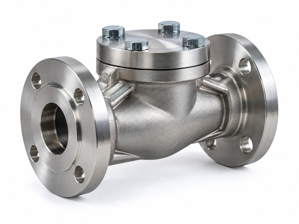
Swing, dual-plate, tilting-disc and axial designs have different moving elements and closing mechanisms. None should be selected solely from a “non-slam” or “low-loss” label.
- Swing check: review disc position at minimum flow, hinge loading, orientation and closing response.
- Dual-plate check: review plate stability, spring configuration, installation orientation and available pressure-loss data.
- Axial or nozzle check: review stable-flow limits, spring and travel configuration, guide arrangement and fluid cleanliness.
- Engineered damped designs: review the complete closure characteristic and maintenance requirements against the system transient.
Some manufacturers offer application-specific springs or travel arrangements. These are engineered options, not field adjustments to make without approval. A change can affect opening, loss and closing performance simultaneously.
For product discussions, compare the stainless steel swing check valve and dual-disc check valve. Request hydraulic confirmation for the quoted model, size and internal configuration; a product-family page is not a low-flow qualification.
7. Check Head Loss and Pump-Trip Response Separately
Ask for pressure loss at minimum, normal and maximum flow. A fully open flow coefficient may not predict low-flow loss when the disc remains partly open. Compare alternatives using applicable curves or validated data for the operating position.
Long periods at typical duty can make modest pressure-loss differences significant for energy use. However, saving head at peak flow does not justify continuous chatter at minimum demand.
A controlled VFD stop is also different from sudden power loss. Val-Matic’s engineering manual explains why preventing check-valve slam does not necessarily remove all pumping-system transient concerns. Where the consequence warrants it, evaluate the valve’s dynamic closure data in a system surge analysis.
Installation matters too. Provide nearby elbows, reducers, pump nozzles and available straight lengths. Obtain model-specific requirements rather than prescribing one generic spacing rule.
8. RFQ Data and Supplier Acceptance Checklist
A useful RFQ connects the pump operating envelope to the valve configuration. Include:
- Fluid, temperature, density, viscosity and expected solids or entrained gas.
- Minimum, normal and maximum flow through each valve, with operating duration.
- Pump curves at relevant speeds, system curve and downstream static head.
- Parallel operation, staging logic, bypass locations and expected flow sharing.
- Pipe internal diameter, flange standard, pressure class, orientation and nearby fittings.
- Allowable pressure loss and maximum/minimum transient conditions.
- Required stable-opening evidence, closure data, materials and leakage acceptance.
- Factory inspection scope and agreed commissioning checks.
Sample Inquiry
Please quote a discharge check valve for the attached variable-speed pump duty table. Confirm the proposed size and internal configuration against each sustained branch-flow condition. State the minimum stable-opening flow, its definition and test or calculation basis; provide pressure-loss data and approved installation requirements. Identify the additional information needed to evaluate pump-trip closure. List deviations and unsupported operating cases separately.
Send Vcore your pump curves, P&ID and operating cases for a project-specific selection review.

9. Commissioning and Related Guides
Agree on commissioning observations at the lowest sustained demand, normal operation and pump staging. Record available flow, pressure, speed and unusual noise or vibration. Investigate a mismatch before treating it as normal behavior. Deliberate trip testing requires an approved commissioning plan; it should not be improvised to demonstrate closure.
Shell and seat tests verify their specified acceptance conditions, but do not by themselves prove stable operation throughout the VFD range. See valve pressure testing methods for those distinctions. For saline duties, add the material and corrosion review in check valve selection for seawater desalination.
10. Frequently Asked Questions
Should the check valve always match the pipe size?
No. Select against flow, pressure loss, stability and installation requirements. A different size may be appropriate, but reducers and peak-duty effects must be included in the review.
Does low cracking pressure guarantee stable low-flow operation?
No. It identifies when opening begins under stated conditions. Stable disc behavior and acceptable loss need separate performance evidence.
Is a spring-assisted check valve always better for a VFD pump?
No. Spring assistance can influence closure, but the exact design must suit the flow range, fluid, orientation and transient. Compare documented performance rather than valve labels.
Will the pump minimum-flow bypass prevent check-valve chatter?
Not necessarily. It depends on where the bypass connects and how much flow passes through the check valve itself.
Can a VFD eliminate water hammer?
A suitable control strategy can moderate normal speed changes, but unplanned trips and other system events still require review. The drive alone is not a complete surge-protection system.
What minimum velocity should be specified?
Use the selected manufacturer’s requirement for the exact valve, fluid and configuration, including the reference area and definition of stability. There is no single value suitable for every check valve.