PTFE Lined Valves During Pipeline Flushing: How to Prevent Lining Damage
A lined valve may be correctly selected for a corrosive process fluid yet face a different challenge during commissioning. Welding residue, metal chips, temporary cleaning chemicals and rapid changes in flow can reach the valve before the plant starts normal service.
This guide addresses flushing preparation and release checks. For flange alignment, gasket selection and bolt tightening during installation or reinstatement, use our PTFE lined valve installation guide.
1. Why Flushing Can Challenge a Chemically Resistant Lining
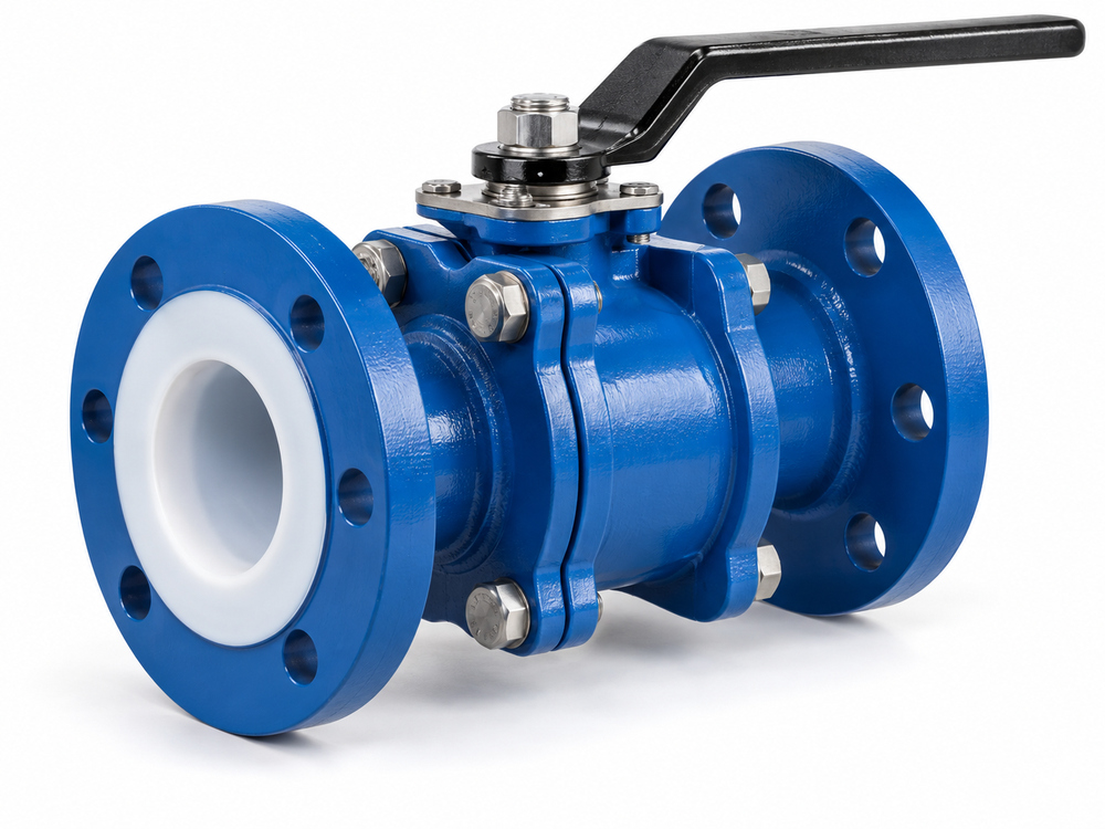
Chemical resistance does not establish resistance to cutting, abrasion or concentrated particle impact. Hard construction debris can contact the lining, lodge near sealing surfaces or become trapped when a closure element moves.
The flushing fluid may also differ from the service medium. Its temperature, cleaning additives and exposure time need review against the actual lining, seats, seals and other wetted components. PTFE, PFA and FEP should not be treated as identical simply because the valve is described commercially as fluoropolymer-lined.
For example, the ChemValve-Schmid PTFE-lined butterfly valve instructions call for an appropriate cleaning fluid and warn that unsuitable cleaning products can harm the valve. This illustrates the need for model-specific instructions rather than a generic compatibility assumption.
2. Decide Which Valves Belong in the Flushing Circuit
Mark the temporary circuit on the P&ID before mobilizing equipment. Identify sensitive valves, instruments, dead legs, return lines and collection points. The decision should account for both the expected debris load and the limits of every retained component.
| Option | When to evaluate it | What must be resolved |
|---|---|---|
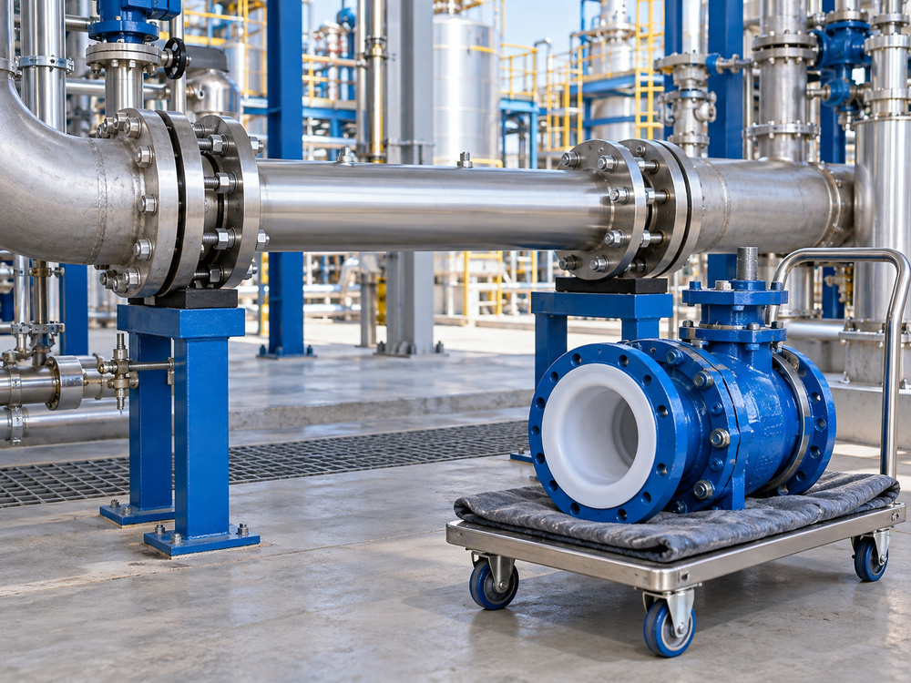
| Remove valve and fit a temporary spool | Heavy fabrication debris or cleaning conditions outside the valve’s approved envelope | Spool rating, materials, supports, isolation, protected valve storage and reinstatement |
| Bypass an isolated valve section | A suitable temporary route can keep the cleaning duty away from sensitive equipment | Positive isolation where required, trapped-fluid management and later cleaning of the excluded section |
| Retain valve in the circuit | The manufacturer accepts the fluid, debris controls and hydraulic/thermal conditions | Approved position, pressure differential, flow direction, monitoring and inspection |
A bypass does not automatically isolate the protected valve. Confirm the boundaries and do not rely on an unverified closed valve to prevent exposure. Likewise, removing a valve creates a separate reinstatement task; document how the clean condition will be maintained until installation.
For proposed PTFE lined ball valves, request the applicable commissioning instructions with the quotation. This allows the temporary spool and access requirements to be planned before construction.
3. Remove Debris Before It Reaches the Lined Surface
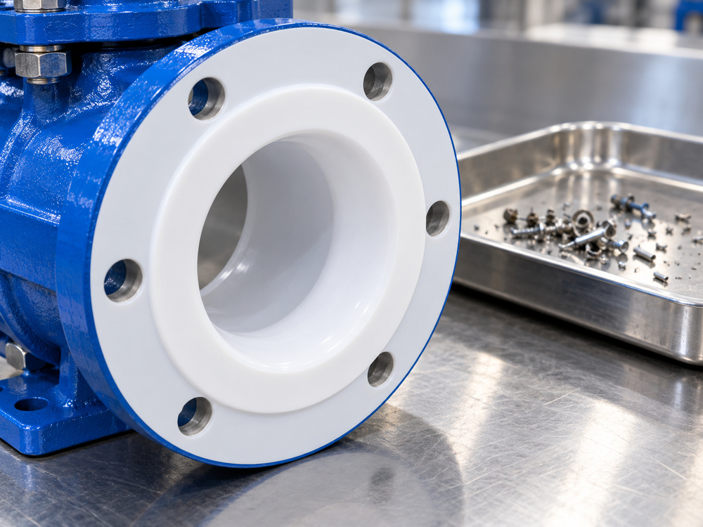
Start with construction cleanliness. Check accessible pipe sections for loose fabrication residue before closing the system. Flushing should not be used to compensate for leaving avoidable quantities of sharp material in a pipeline.
CRANE’s TUFLINE lined plug valve operating instructions specifically address careful flushing to remove hard particulates before pressure testing. Follow the applicable project sequence and the instructions for the installed valve model.
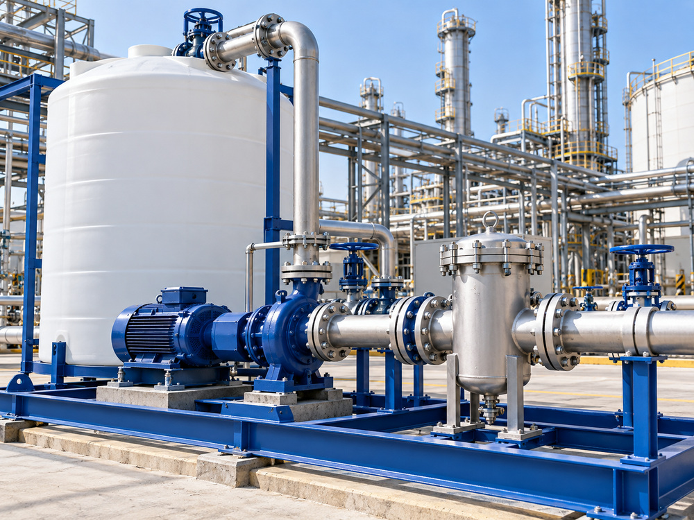
If temporary strainers or filters are proposed, define where they intercept debris, what they can retain and how their condition will be monitored. A downstream collector may show what has already passed through the valve; it does not protect that valve from the first impact.
- Specify expected particle type, approximate size and loading rather than only “dirty water.”
- Evaluate strainer pressure drop, capacity, mechanical rating and the effect of blockage.
- Provide a controlled shutdown and cleaning method for loaded temporary equipment.
- Prevent collected material from returning through a recirculating flushing loop.
No filter rating guarantees protection from every particle or dissolved contaminant. The collection method must support the agreed cleanliness objective without creating an unacceptable pressure differential.
4. Set Valve Positions for the Actual Design
Do not write one instruction such as “leave all valves half open” for a mixed piping system. Different closure elements create different obstructions, pockets and sealing interfaces.
| Valve type | Flushing review focus |
|---|---|
| Lined ball or plug valve | Manufacturer-approved opening, cavity exposure and whether any controlled movement is required |
| Lined butterfly valve | Disc remains in the flow path even when open; review particle impact, clearance and permitted position |
| Lined diaphragm valve | Required travel, diaphragm limits, retained spaces and approved cleaning conditions |
| Lined check valve | Permitted flow direction, stable opening and possible chatter or debris trapped at the seat |
Do not use an on-off lined valve as the temporary flow-control restriction unless that duty is explicitly approved. A partly open passage can concentrate velocity and particle impact in a small area.
Avoid repeatedly cycling a valve through known hard debris as an improvised cleaning method. If a manufacturer’s procedure requires movement during cleaning, follow its specified conditions. Unexpected operating resistance calls for assessment, not extra actuator force or a longer hand lever.
For automatic non-return duties, review the PTFE lined check valve separately. It should not be forced open or exposed to reverse flushing without an approved arrangement.
5. Approve the Complete Flushing Envelope
The normal datasheet may not describe the temporary cleaning duty. Submit the proposed conditions to the valve supplier before flushing begins:
- Fluid and additives: composition, concentration, temperature and exposure duration.
- Flow: expected range, direction and any intermittent or pulsed operation.
- Pressure: maximum line pressure, valve differential and credible surge conditions.
- Temperature: maximum value and planned heating/cooling changes.
- Vacuum: possible low pressure during drainage, cooling or connected equipment operation.
- Cleaning method: liquid circulation, gas blowing, steam, mechanical tools or other proposed treatment.
There is no universal safe flushing velocity for all lined valves. Geometry, fluid, debris and the specific lining construction matter. If the cleaning objective needs conditions outside the approved envelope, redesign the temporary circuit instead of assuming a short exposure will be harmless.
Review drainage and cooldown as well as pumping. A lining that tolerates positive pressure may have different vacuum limitations. The engineer should evaluate venting, trapped volumes and how the circuit returns to a safe unpressurized condition.
6. Protect Valves Removed for Flushing
Record valve tags and original orientation, then protect the lined flange faces and bore with clean compatible covers. Support the valve securely and keep dirt, grinding residue and sharp tools away from exposed surfaces.
Do not scrape a lining with metal tools or treat it like a bare steel bore. Any mechanical cleaning, solvent use or proposed local repair needs the manufacturer’s acceptance. Welding and heat exposure near a lined assembly require particular care and the relevant installation restrictions.
Before reinstatement, verify that the adjacent pipe section is clean and that temporary equipment has been removed as intended. Follow the linked installation guide and the model-specific manual for alignment, flange compatibility, gaskets and tightening requirements.
7. Inspect and Release the Valve After Flushing
Define acceptance before the work starts. Clear-looking discharge water alone does not prove lining integrity or seat tightness. The release record should combine circuit cleanliness evidence with the required valve checks.
- Confirm isolation, depressurization, safe temperature and decontamination before opening equipment.
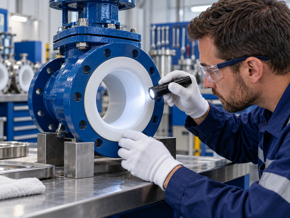
- Inspect accessible lining and flange faces for new cuts, gouges, blisters, lifting, deformation or embedded particles.
- Record inaccessible areas and any need for manufacturer-approved further inspection.
- Check operation under approved conditions and investigate abnormal resistance or incomplete travel.
- Perform the specified leakage or functional verification and record the method and result.
- Restore the correct configuration, remove temporary items and close outstanding deviations before process release.
A pressure test does not by itself demonstrate that the lining is undamaged. Likewise, a visual check cannot detect every discontinuity. If holiday or spark testing is required, use an approved method, voltage and scope suitable for the actual lining; an arbitrary electrical test can damage the material. See valve pressure testing methods for the distinction between inspection objectives.
Suspected lining damage should be referred for a documented disposition. Do not sand, trim, heat or patch the surface simply to obtain a passing seat test.
8. Procurement and Commissioning Checklist
Request the information needed to plan flushing when purchasing the valve, not after the cleaning contractor arrives.
Suggested Supplier Request
Please confirm the permitted pipeline-flushing conditions for the quoted lined valve. Review the attached cleaning fluid, concentration, temperature, flow range, pressure differential, expected debris, operating direction and possible vacuum. Identify the required valve position, any approved cycling sequence and conditions that require removal or bypass.
Provide handling and reinstatement instructions, post-flushing inspection requirements, applicable lining-integrity test limitations and the recommended response to suspected damage. List any conditions not covered by the supplied valve documentation.
Send Vcore your valve datasheet and proposed flushing plan for configuration-specific review.
Assign responsibility for the marked-up circuit, supplier review, temporary equipment ratings, monitoring, debris disposal and final reinstatement. Keep records of departures from the approved procedure, including unexpected temperature, differential pressure or operating resistance.
9. Related Products and Technical Guides
- PTFE lined plug valve — review the selected design’s commissioning and cleaning instructions.
- PTFE lined ball valve — discuss temporary flushing duty alongside normal process conditions.
- PTFE lined valve installation — flange, gasket and tightening considerations for reinstatement.
- Industrial valves for chemical processing — the broader material and service-selection framework.
10. Frequently Asked Questions
Should every PTFE lined valve be removed before flushing?
No universal rule applies. Assess the debris and cleaning conditions against the manufacturer’s instructions. Removal or an engineered bypass may be appropriate when the temporary duty cannot be accepted for the valve.
Is fully open always the correct flushing position?
No. Confirm the position for the valve type and cleaning procedure. A fully open butterfly disc remains in the flow, and an open ball valve may still have spaces requiring separate consideration.
Can a temporary strainer eliminate lining damage?
No. It can reduce selected debris exposure when correctly located and maintained, but does not address every particle, chemical, thermal or pressure-related risk.
Can I use steam to clean a PTFE lined valve?
Only if the actual valve assembly and procedure are approved for that duty. Check temperature, pressure, heating/cooling conditions and the possibility of vacuum during condensation.
Does a successful pressure test prove the lining survived flushing?
No. Pressure integrity, lining condition and seat tightness are separate checks. Use the inspection and acceptance methods specified for the supplied valve.
What should happen if operating torque rises after flushing?
Stop forcing the valve and arrange assessment under safe isolated conditions. Debris, installation stress or damage may be involved; increasing actuator output can worsen the problem.