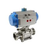
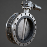
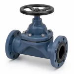
A steam pressure reducing and desuperheating system (PRDS) controls two different steam properties: pressure and temperature. The steam-side pressure-reducing control valve establishes downstream pressure, while a desuperheater and spray-water control valve reduce steam temperature by injecting and evaporating cooling water. Correct selection requires inlet and outlet steam pressure, inlet and target outlet temperature, minimum/normal/maximum steam flow, spray-water pressure and temperature, turndown, noise limits, piping geometry, mixing distance, sensor location, actuator duty and startup or low-load conditions.
Power & Steam · Steam Conditioning Station Design Review
Steam PRDS Valve Selection: Pressure Reducing and Desuperheating System Guide
A PRDS is not simply a pressure-reducing valve with a water connection. It is a coordinated steam-conditioning station. Pressure reduction changes the steam thermodynamic state, while desuperheating uses controlled water injection to reach the required downstream temperature. The valve package, desuperheater, spray-water system, piping and control loops must therefore be reviewed as one operating system.
PRDS Functional Architecture
The arrangement below is a functional design map, not a universal plant P&ID. Actual valve order, isolation philosophy, bypasses, drains, safety devices and instrumentation must follow the approved project design.
P1 · T1 · Flow
Pressure loop
Water injection & mixing
P2 · T2 target
Two different variables are being controlled: downstream steam pressure and downstream steam temperature. That distinction should remain clear in valve sizing, instrumentation and troubleshooting.
Pressure Reduction and Desuperheating Are Different Control Duties
STEAM-SIDE DUTY
Pressure-Reducing Control
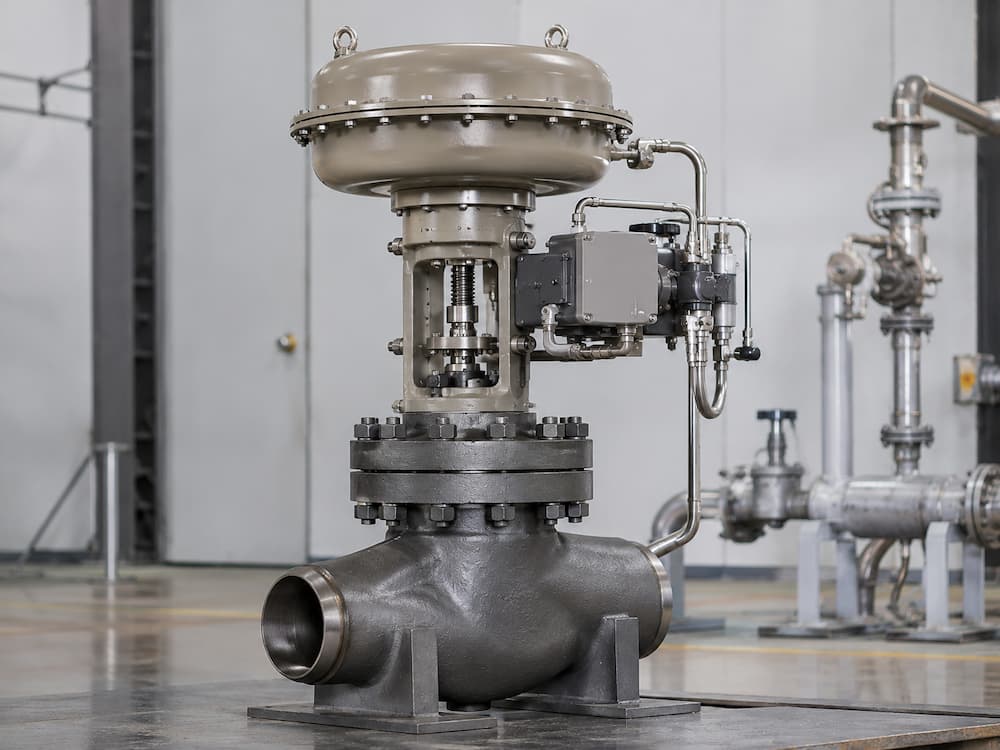
The steam control valve throttles high-pressure steam to the required downstream pressure. Its selection depends on compressible-flow sizing, pressure ratio, minimum-to-maximum flow, choked-flow potential, aerodynamic noise, outlet velocity, trim design and actuator force.
Control target: downstream pressure.
WATER-SIDE DUTY
Desuperheating / Temperature Control
The desuperheating system adds controlled cooling water to the steam. The spray-water control valve meters water; the desuperheater or nozzles atomize and distribute it; downstream piping provides evaporation and mixing distance.
Control target: downstream steam temperature.
A pressure-reducing valve cannot guarantee outlet steam temperature by itself, and a spray-water valve cannot establish downstream steam pressure. PRDS performance depends on both loops and the physical mixing system.
Why Steam Can Remain Superheated After Pressure Reduction
Throttling changes steam pressure without directly removing enough energy to force the outlet state to the saturation line. Depending on the inlet state and pressure reduction, steam leaving the pressure-reducing valve can remain superheated. Desuperheating then removes additional sensible heat by evaporating controlled spray water.
Before PRDS
After throttling
After desuperheating
Do not specify “saturated steam” casually. The final outlet condition should come from the process designer. Excessive water injection or insufficient evaporation distance can create wetting or wet-steam risk downstream.
DESIGN STATION A
Pressure-Reducing Control Valve Selection
The steam-side valve is usually the highest-energy throttling component in a PRDS station. Selection should start with minimum, normal and maximum steam flow rather than pipe size.
| Review Item | Why It Matters |
|---|---|
| P1 / P2 for each case | Determines pressure ratio, capacity and severity. |
| Steam temperature / superheat | Affects thermodynamic properties, materials and downstream conditioning. |
| Min / normal / max flow | Prevents a valve that works only at one operating point. |
| Predicted travel | Checks minimum-load controllability and useful normal-load position. |
| Noise / outlet velocity | High-energy steam expansion can create aerodynamic noise and vibration. |
| Actuator force / fail action | Must match pressure forces, trim balance and project shutdown philosophy. |
Related product pages: Steam Control Valve and High Pressure Control Valve. For sizing methodology, see How to Size a Control Valve.
DESIGN STATION B
Desuperheater and Spray-Water Control
The water-side control valve meters cooling water; it does not perform atomization by itself. Atomization and evaporation depend on the desuperheater/nozzle design, spray-water pressure differential, steam velocity, droplet size, downstream pipe geometry and mixing distance.
Water Valve
Controls water mass flow and must provide stable low-flow response, appropriate Cv/Kv, cavitation resistance and required shut-off.
Nozzle / Desuperheater
Creates the spray pattern and droplet distribution needed for evaporation into the steam stream.
Downstream Piping
Provides velocity, residence time and mixing distance before temperature measurement or sensitive equipment.
For detailed water-valve selection, use the existing Spray Water Control Valve page rather than duplicating that product content here.
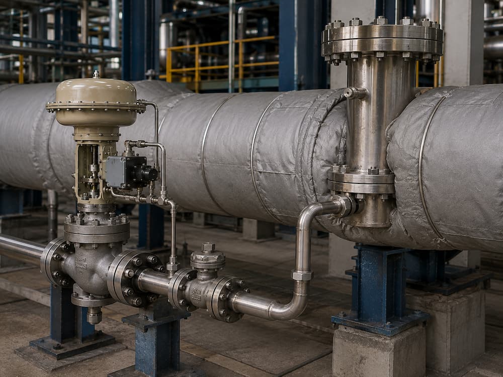
Spray-Water Pressure: Use the Nozzle Requirement, Not a Universal Rule
Spray water must reach and pass through the selected injection device under the worst operating condition. The required pressure margin depends on desuperheater type, nozzle design, steam pressure at the injection point, piping loss, water control-valve pressure drop and atomization method.
Do not publish a fixed rule such as “spray water must always be X bar above steam pressure.”
The minimum required differential pressure should come from the selected desuperheater/nozzle design and the complete water-side hydraulic calculation.
Two Control Loops — One Conditioned Steam Outlet
| Loop | Measured Variable | Final Element | Main Risk |
|---|---|---|---|
| Pressure | Downstream steam pressure | Steam control valve | Poor pressure control, hunting, noise or wrong outlet pressure. |
| Temperature | Steam temperature after adequate mixing | Spray-water control valve | Oscillation, over-spray, unevaporated water or insufficient cooling. |
Sensor location matters. A temperature sensor positioned before sufficient evaporation and mixing can report a condition that does not represent the final steam state.
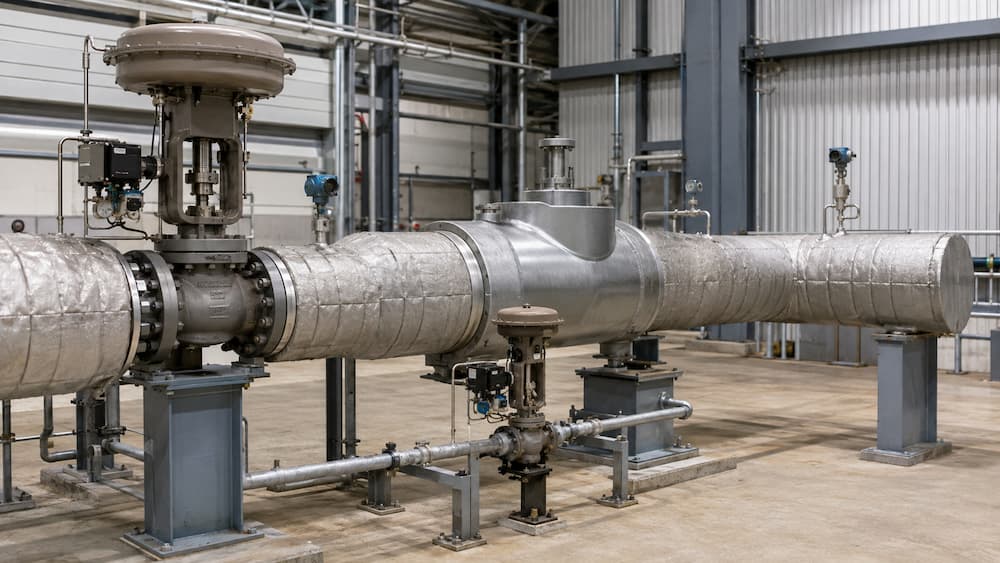
Split PRDS vs Combined Steam Conditioning Valve
ARCHITECTURE A
Split PRDS
The pressure-reducing valve and desuperheater are separate devices. A separate spray-water control valve regulates cooling water.
Review: equipment spacing, straight pipe, mixing distance, sensor location, maintenance access and coordination between suppliers.
ARCHITECTURE B
Combined Steam Conditioning Valve
Pressure reduction and water injection are integrated into one valve body or closely integrated assembly.
Review: integrated trim/nozzle design, turndown, noise, maintenance, injection geometry and outlet piping.
Neither architecture is universally better. Plant layout, operating range, steam conditions, maintenance philosophy and supplier design determine the appropriate configuration.
Low-Load Operation Can Be the Hardest Condition
At low steam flow, required spray-water flow can become very small and steam velocity may be less favorable for atomization and evaporation. At the same time, an oversized pressure-reducing valve may operate near the bottom of its useful travel.
Steam valve
Water valve
Atomization
Downstream
PRDS RFQs should therefore include minimum operating flow, not only normal and maximum steam flow.
PRDS vs Pressure-Reducing Valve vs Desuperheater
| Equipment | Primary Function | Does Not Automatically Provide |
|---|---|---|
| Steam pressure-reducing valve | Controls downstream pressure. | Controlled outlet temperature. |
| Desuperheater | Injects / atomizes water for cooling. | Steam pressure control. |
| Spray-water control valve | Meters cooling water. | Atomization or complete mixing by itself. |
| PRDS | Coordinates pressure and temperature reduction. | Correct piping, sensing, commissioning and operating logic are still required. |
Turbine Bypass: Related, but Not the Same Specification
Turbine bypass systems often require severe steam pressure reduction and desuperheating during startup, shutdown, trip or load-management conditions. However, turbine-bypass service can involve much more severe dynamic requirements than a general process PRDS.
- Large and rapidly changing steam mass flow
- Very high pressure ratio
- Strict opening or closure time requirements
- High aerodynamic noise and vibration risk
- Fast coordination between steam and spray-water systems
- Project-specific downstream steam system or condenser conditions
Do not automatically market a general PRDS valve as a turbine-bypass valve. The bypass duty must be checked against the project transient, actuator dynamics, downstream system and OEM/EPC specification.
PRDS RFQ Datasheet — Minimum Engineering Inputs
Upstream Steam
- Minimum / normal / maximum steam flow
- P1 for each case
- T1 for each case
- Steam condition / superheat
- Design pressure and temperature
Required Outlet
- Required P2
- Target T2
- Residual superheat if specified
- Allowable pressure / temperature deviation
- Downstream line size and equipment limits
Spray Water
- Available water pressure
- Water temperature
- Minimum / maximum available flow
- Water quality requirement
- Water-line size
Control & Piping
- Split or combined PRDS preference
- Available straight pipe length
- Pressure / temperature sensor locations
- Actuator, signal and fail action
- Maximum noise if specified
- Required opening / closure time
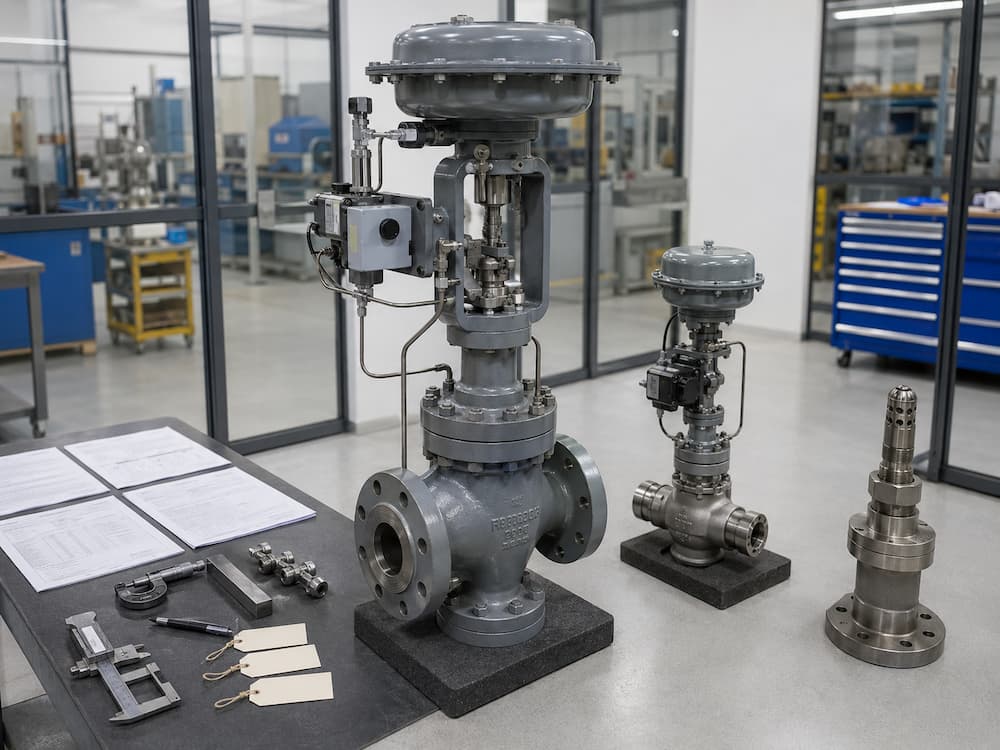
Factory and Project Verification
| Verification | Status | Purpose |
|---|---|---|
| Valve sizing calculation | Required | Verify steam and water valves against stated cases. |
| Actuator sizing / stroke check | Required | Confirm force, travel and fail action. |
| Material / pressure-test records | As specified | Verify agreed pressure-containing scope. |
| Noise prediction | Project dependent | Review high-energy steam expansion. |
| Desuperheater performance review | Project dependent | Confirm nozzle, water ΔP, mixing distance and turndown. |
| Integrated commissioning | Site / project scope | Confirm final pressure and temperature control in the installed system. |
Factory valve tests do not by themselves prove final PRDS outlet temperature, atomization quality or site control-loop performance. These also depend on the installed desuperheater, piping, sensors, water supply and commissioning.
Related Technical Resources
Technical References
Frequently Asked Questions
What is a steam PRDS?
A steam PRDS is a pressure reducing and desuperheating system used to reduce high-pressure superheated steam to a lower controlled pressure and temperature. It typically combines a steam pressure-reducing control valve, a desuperheater, a spray-water control valve and pressure/temperature control instrumentation.
Is PRDS the same as a pressure reducing valve?
No. A pressure reducing valve controls steam pressure. A PRDS also includes temperature reduction, so it requires a desuperheating system, cooling-water control and temperature feedback.
Why is desuperheating needed after pressure reduction?
Steam can remain superheated after throttling to a lower pressure. Desuperheating removes additional sensible heat by evaporating controlled spray water until the required outlet temperature is reached.
Does the spray-water control valve atomize the water?
Not by itself. The valve meters water flow. Atomization is performed by the desuperheater or nozzle arrangement, and final evaporation also depends on steam velocity, injection pressure, piping geometry and mixing distance.
How much higher should spray-water pressure be than steam pressure?
There is no universal pressure margin. The required water pressure depends on the nozzle/desuperheater design, steam pressure at the injection point, water-line losses, control-valve pressure drop and atomization method.
What is the difference between split and combined PRDS?
A split PRDS uses a separate pressure-reducing valve and downstream desuperheater. A combined steam-conditioning valve integrates pressure reduction and water injection more closely in one valve body or compact assembly.
Why can PRDS control become unstable at low steam flow?
At low steam flow, required spray-water quantity can become very small and steam velocity may be less favorable for atomization and evaporation. This can challenge water-valve rangeability, nozzle performance and temperature measurement stability.
Is a general PRDS suitable for turbine bypass service?
Not automatically. Turbine bypass can require very large pressure reduction, fast transients, high noise attenuation, rapid actuator response and tightly coordinated spray-water injection. It must be checked against the project-specific turbine bypass duty.
What information is needed for a PRDS quotation?
Provide minimum, normal and maximum steam flow; inlet and required outlet steam pressure; inlet and target outlet temperature; design pressure and temperature; spray-water pressure, temperature and flow; line sizes; noise requirement; actuator/fail action; and available piping or turbine-bypass requirements.