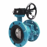
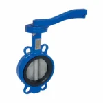
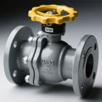
A terminal or pump-station RFQ may describe a ball valve simply as “DN100, Class 150, for gasoline.” That description leaves important decisions to the supplier: whether the fuel contains ethanol, which body seals are acceptable, what happens on loss of power, and what evidence is required for fire-tested performance.
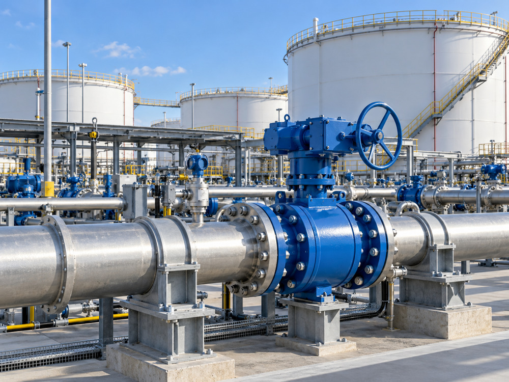
This procurement checklist turns those missing details into reviewable RFQ items. It covers liquid gasoline transfer between tanks, pumps and loading facilities. Gasoline is not natural gas, LPG or diesel; specify the actual liquid service. For wider facility planning, see Vcore’s petroleum valve solutions.
1. Define the Gasoline Blend Before Choosing Seals
“Gasoline” is a family of fuel mixtures, not a single chemical. Provide the fuel specification and current safety data sheet, together with the expected composition range. An SDS may not disclose every component or concentration needed for material selection, so obtain additional blend information when necessary.
| Fuel information | What the buyer should provide | Procurement consequence |
|---|---|---|
| Fuel identity | Motor gasoline, blendstock or another specifically identified fuel | Prevents selection against a different hydrocarbon service. |
| Ethanol and oxygenates | Specified blend and maximum concentration; other oxygenates if present | Changes the chemical exposure of elastomeric seals. |
| Hydrocarbon composition | Relevant aromatic content and supplier fuel specification | Supports compound-specific compatibility review. |
| Water and contamination | Expected water, particulates and abnormal contamination | Affects corrosion, seat wear and suitability. |
| Additives and other fluids | Additive packages, cleaning agents and flushing fluids | All expected exposures must be reviewed. |
| Future operating range | Permitted fuel grade changes and blend variation | Avoids approval for only one nominal blend. |
For example, if a line normally carries E10 but may later receive a higher-ethanol blend, state the complete expected range before ordering. Do not assume approval for one fuel grade transfers to all gasoline blends.
Review the Compound, Not Just the Rubber Family
A quote listing “FKM seals” or “NBR seals” is not a complete compatibility statement. Compound formulation, temperature, exposure time and static or dynamic use affect performance. Ask the supplier to identify the actual seal compound or its controlled specification and confirm suitability for the stated blend and temperature range.
A generic compatibility chart is a useful screening tool, but final approval should relate to the supplied compound and valve duty. Where blend variation or uncertain compatibility matters, request relevant manufacturer data or agreed testing before technical release.

2. State Operating, Design and Pump Isolation Conditions
Provide normal and design pressure and temperature, their units and whether pressure is gauge or absolute. Include minimum ambient temperature and credible operating cases. Outdoor equipment may experience cold weather, solar heating and long periods without flow.
Ask the project engineer to identify the pressure the valve must contain when the pump discharge is blocked, including the applicable pump shut-off condition, relief arrangement and design basis. Do not select the valve from normal discharge pressure alone.
- Normal upstream and downstream pressure.
- Maximum required pressure differential during opening and closing.
- Specified design pressure–temperature combinations.
- Expected flow, duty cycle and frequency of operation.
- Start-up, shutdown, reverse-flow and vacuum cases where relevant.
- Surge conditions and required closure-time limits.
Check the complete valve rating at the specified temperature using our pressure–temperature rating guide. A Class marking or cold test pressure is not a substitute for a configuration-specific operating rating.
3. Specify the Complete Sealing Configuration
The primary seats are only part of the sealing system. Gasoline also contacts or can reach body-joint seals, stem seals, packing, seat O-rings and cavity-port seals, depending on construction. Request a complete bill of materials rather than accepting “PTFE seat” as the whole sealing description.
| Component | RFQ requirement | Evidence to review |
|---|---|---|
| Primary seats | Material, grade or controlled specification and required leakage performance | Compatibility and pressure–temperature limits. |
| Body seals and O-rings | Exact material specification for all wetted seals | Approval for fuel, additives and flushing fluids. |
| Stem packing | Normal leakage control and any specified emissions qualification | Applicable qualification scope and assembly details. |
| Metallic wetted parts | Body, ball and stem grades; coatings where applicable | Material traceability and corrosion review. |
| Cavity fittings | Drain, vent or relief arrangement where required | Pressure rating, seal compatibility and approved routing. |
State the leakage test standard, medium, pressure, direction and acceptance criteria required by the project. “Bubble tight” without a defined test is too vague for comparing quotations. Fugitive-emissions qualification, if specified, concerns external leakage and does not replace a seat shut-off test.
Clarify Cavity Pressure and Isolation Direction
Liquid trapped in a closed valve cavity can increase in pressure as it warms. Ask how the proposed design manages cavity pressure, whether relief is internal or external, and where it discharges. Any external discharge must follow the project’s approved containment arrangement.
Confirm whether the required isolation is unidirectional, bidirectional, double block and bleed or another defined arrangement. Cavity relief and seat direction can affect isolation behavior. For a project requesting two barriers and a bleed point, review our double block and bleed valve configuration and verify the actual seat arrangement; the DBB label alone does not approve a maintenance isolation procedure.
4. Define Connections, Bore and Installation Dimensions
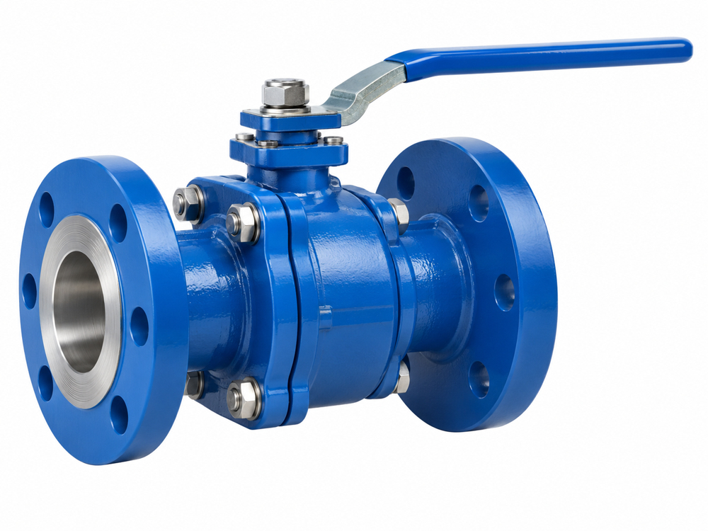
Specify DN or NPS together with the exact end standard and rating. “ANSI flange” or “PN flange” is insufficient. Identify the applicable standard, facing, drilling, gasket interface and face-to-face requirement. For welded ends, provide the pipe outside diameter, wall thickness or schedule and required weld preparation.
Full bore may be requested to reduce restriction or accommodate a project requirement. If pigging is involved, specify the actual required through-bore diameter and geometry; a catalogue “full bore” label is not enough. Review the valve’s flow capacity and allowable pressure loss for the transfer duty.
- Flange standard, rating, facing and mating flange details.
- Face-to-face or end-to-end dimensions and installation envelope.
- Bore diameter and any pigging requirement.
- Drain, vent and instrument connection sizes and orientation.
- Actuator clearance, support needs and maintenance access.
- Permitted installation orientation and flow direction.
Connection type should follow the approved piping specification and maintenance strategy. Do not assume threaded, welded or flanged construction is universally acceptable at every terminal. For larger transfer lines, our trunnion ball valve page provides a starting point for a configuration enquiry.
5. Choose the Operating Method From the Actual Duty
| Operation | Suitable enquiry context | Details to confirm |
|---|---|---|
| Lever or gearbox | Accessible local isolation | Operating effort, locking, position indication and access. |
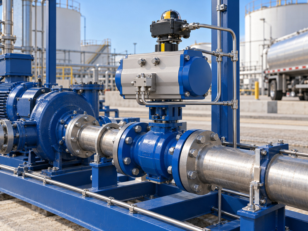
| Pneumatic | Remote isolation or project-defined shutdown duty | Air supply, fail action, torque, accessories and stroke time. |
| Electric | Remote operation with specified power availability | Voltage, duty, controls, loss-of-power behavior and area approval. |
| Hydraulic or packaged system | Duty requiring a project-selected drive arrangement | Supply, stored energy, fail action and package interfaces. |
Size the actuator using the valve supplier’s torque data for the governing pressure differential, temperature and operating cases. Confirm minimum available air pressure or electrical supply, the project sizing allowance and the effect of prolonged idle periods.
For emergency shutdown, state what must happen on loss of signal, air or electrical power. “Fail close” must be supported by the actual actuator and accessory arrangement. A standard electric actuator does not automatically close when power disappears.
Do not select the fastest closing valve by default. Rapid closure can contribute to surge in a liquid transfer line. Agree closure time with the project hydraulic and shutdown requirements. If the line requires continuous flow regulation, request a control-valve review rather than assuming an isolation ball valve is suitable for throttling. See our pneumatically actuated ball valve for automated isolation enquiries.
6. Verify Fire-Test Evidence When the Project Requires It
If the project requires a fire-tested valve, name the required standard and edition in the RFQ. API 607, API 6FA or ISO 10497 may be specified depending on the valve and project requirements. Do not treat their names as interchangeable purchasing labels.
Request the certificate or report reference, tested design identification and the permitted qualification coverage. Review the offered model, size, pressure class, materials, seat and sealing design against the tested configuration and the standard’s extension rules. A supplier’s certificate for an unrelated valve is not sufficient evidence.
A fire type test evaluates performance under defined test conditions and leakage limits. It does not mean zero leakage under every real fire, and it does not establish the suitability of the entire automated shutdown package.
For model-specific enquiries, see our fire safe ball valve. Required evidence must be confirmed for the selected configuration before purchase.
7. Specify Anti-Static and Hazardous-Area Requirements Separately
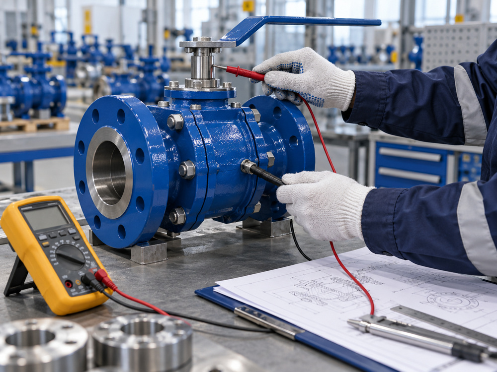
Where required, an anti-static valve design provides electrical continuity between designated conductive parts, commonly the ball, stem and body. Identify the governing valve standard, test method, measurement points and acceptance criterion. Request verification records at the inspection scope required by the project.
Do not invent one resistance limit for every valve or assume the handle provides the necessary conductive path. Internal valve continuity does not replace terminal piping bonding, earthing or the site’s static-control measures.
For an automated assembly, provide the area classification and jurisdiction-specific certification requirements for the actuator, solenoid, limit switches, positioner and other electrical accessories. Relevant details can include gas group, temperature class, equipment protection level or category, ambient range and enclosure protection, as applicable.
ATEX, IECEx and other approval schemes must be selected for the project jurisdiction and area classification. An electrical accessory’s approval does not certify the valve’s fire-tested sealing performance, and a valve fire-test certificate does not approve electrical equipment for a hazardous location.
8. Agree Documents and Inspection Before the Order
Use a document register with submission dates, review status and final release requirements. Identify which records are required for each tag or serial number, and which are design-qualification records covering a product family.
| Document or record | Purpose | Buyer check |
|---|---|---|
| Datasheet and bill of materials | Defines the offered configuration | Complete materials and explicit deviations. |
| General arrangement drawing | Confirms installation and interfaces | Connections, dimensions, orientation and access. |
| Material certificates | Supports material traceability | Agreed certificate type and identification. |
| Pressure and seat test reports | Records specified production tests | Standard, medium, pressures and acceptance. |
| Fire-test qualification | Supports specified fire-tested design | Coverage of the offered configuration. |
| Anti-static evidence | Verifies specified continuity requirement | Method, points, acceptance and required inspection scope. |
| Actuator package documents | Defines operation and interfaces | Torque sizing, wiring, pneumatics, fail action and approvals. |
| Emissions qualification, if specified | Supports required external leakage performance | Qualification scope and supplied packing arrangement. |
| Installation and maintenance manual | Supports handling and operation | Fuel compatibility restrictions and maintenance instructions. |
Set review and witness points using our valve inspection and test plan guide. For final release, consult the factory acceptance test guide and valve certificates and quality documents guide.
State whether independent inspection, special testing, a particular certificate type or country-of-origin documentation is required. These items can affect quotation cost and delivery; they should be agreed before production.
Compare Quotations on a Common Technical Basis
Mark each requirement as confirmed, deviated, excluded or awaiting evidence. Compare price only after reviewing fuel compatibility, the complete configuration, rating, connections, operation and qualification coverage.
- Hold: the quote says “suitable for gasoline” but does not identify the blend or all wetted seals.
- Hold: fire-safe or anti-static is claimed without the required supporting evidence.
- Resolve: actuator fail action or closure time differs from the project specification.
- Proceed with review: the exact configuration is defined, evidence is applicable and deviations are formally accepted.
RFQ Text for a Gasoline Transfer Ball Valve
Please quote ball valves for liquid gasoline transfer at our terminal/pump station, against the attached fuel specification, SDS, valve datasheet and piping requirements.
Please confirm compatibility of all wetted materials and seals with the specified fuel composition and blend range. State the complete pressure–temperature rating, bore, connections, seat arrangement, cavity-pressure management and leakage test basis.
For actuated valves, provide torque sizing, fail action, stroke time and accessory details. Confirm compliance with the specified fire-test, anti-static and hazardous-area requirements, and provide applicable qualification evidence and document scope. List all deviations, exclusions, lead time and inspection costs separately.
Frequently Asked Questions
Is an oil-service ball valve automatically suitable for gasoline?
No. Review the actual gasoline blend, all wetted materials and seals, operating conditions and project requirements.
Does PTFE seating prove ethanol-blended gasoline compatibility?
No. Seats are only part of the sealing system. Body seals, O-rings and stem sealing materials also need configuration-specific approval.
Does a fire-safe valve certificate include anti-static compliance?
Do not assume it does. Review the separate requirements and their supporting evidence.
Must every gasoline valve have the same fire-test standard?
The owner specification, applicable requirements and accepted valve qualification determine the required standard and edition. Confirm them in the RFQ.
Is fail-close always the correct shutdown action?
The project shutdown philosophy determines the required action. Confirm it together with surge considerations and the actual actuator package.
Send Vcore Your Gasoline Transfer Requirements
Send the fuel composition range, size, pressure–temperature duty, connections, operating method and project documentation requirements with your enquiry. Vcore can review the proposed ball valve configuration against those requirements before finalizing the quotation. Contact Vcore Valve with your valve list and project specification.
Technical References
- Parker O-Ring Handbook — compound selection and compatibility guidance; use material-manufacturer confirmation for the actual supplied seals.
- API refining standards catalogue — API 607 fire-test scope and distinction from actuator protection. Apply the project-specified standard edition.
- API standards catalogue — identify the required product, inspection and qualification standards.