Control valve rangeability and process turndown are related but not interchangeable. Inherent rangeability describes a valve’s flow characteristic under defined test conditions, while process turndown describes the ratio between the required maximum and minimum operating flow. The installed controllable range can be narrower because valve pressure drop changes with load, normal travel is too low, actuator or positioner resolution is inadequate, friction creates deadband, or the process measurement cannot resolve the minimum flow. Buyers should verify the complete operating envelope using minimum, normal and maximum process cases rather than accepting one catalogue rangeability ratio as proof of plant performance.
Operating Envelope Audit
Control Valve Rangeability vs Process Turndown
A process requires 100 units of flow at peak load and 5 units at minimum load. The process turndown is 20:1. A supplier offers a valve with a stated rangeability of 50:1. Does that prove the valve can control the process from 5 to 100 units? No. The project still has to prove the installed hydraulic, mechanical and measurement limits.
Four Terms That Must Not Be Mixed Together
TERM 01
Process Turndown
The required maximum operating flow divided by the required minimum operating flow.
TERM 02
Inherent Rangeability
A valve characteristic term established under defined test conditions, commonly expressed as the ratio between the largest and smallest controllable flow coefficient within stated characteristic limits.
TERM 03
Installed Range
The part of the real system operating range over which the installed valve, actuator, positioner, measurement and process can maintain acceptable control.
TERM 04
Usable Travel Window
The actual valve travel region available for stable modulation after seat approach, full-open limitation, deadband, friction and severe-service restrictions are considered.
A quoted rangeability ratio should always be tied to a defined valve design, trim, characteristic, test basis and allowable deviation. It should not be treated as a universal installed performance guarantee.
The Control Envelope Has Four Boundaries
The valve is suitable only when all four boundaries are acceptable at the same time.
BOUNDARY A
Maximum Capacity
At maximum demand, the valve must pass the required flow without depending on impossible travel, unavailable pressure drop or unacceptable choked-flow conditions.
Evidence: Maximum flow case, P1, P2, fluid properties, required Cv/Kv and predicted travel.
BOUNDARY B
Minimum Controllable Flow
At minimum demand, the valve must provide enough usable travel and flow resolution without operating in a region dominated by seat effects, friction or excessive gain.
Evidence: Minimum flow case, predicted travel, smallest repeatable movement and process measurement resolution.
BOUNDARY C
Mechanical Resolution
The actuator and positioner must overcome friction and move the trim in small, repeatable increments in both directions.
Evidence: Command vs actual travel, deadband, hysteresis, stiction, actuator force and feedback performance.
BOUNDARY D
Installed Hydraulic Behavior
The pressure drop across the valve changes as the system load changes. This can alter the installed flow characteristic and the gain available at different travel positions.
Evidence: System pressure-loss distribution, valve authority, pump or compressor behavior and installed characteristic review.
Why a Catalogue Rangeability Ratio Is Not Enough
Inherent rangeability is associated with the valve’s inherent flow characteristic under defined conditions. Installed service adds piping losses, equipment losses, changing pump or compressor head, varying downstream pressure, measurement limitations and actuator behavior.
The installed valve may therefore lose useful control range even though the trim itself has a high stated inherent rangeability.
A High Ratio Can Still Fail at Minimum Flow
If the valve is oversized, minimum and normal flow may occur very close to the seat. The theoretical trim characteristic may extend lower, but actual control can be limited by seat contact, friction, backlash, leakage, process noise or poor measurement resolution.
A High Ratio Can Still Fail at Maximum Flow
If the system does not provide the assumed valve pressure drop, the valve may reach full travel without delivering the required maximum flow. Increasing the stated rangeability does not correct missing capacity.
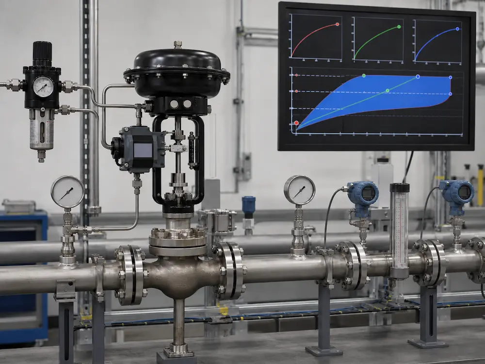
Audit Minimum, Normal and Maximum Cases Separately
CASE 01
Minimum Flow
Main question: Can the final control element make a small, repeatable change that the process can measure?
- Predicted valve travel
- Seat and leakage behavior
- Stiction and deadband
- Position feedback resolution
- Flowmeter range and accuracy
- Minimum stable pump or process condition
CASE 02
Normal Flow
Main question: Does normal operation remain in a stable, useful travel region with acceptable gain?
- Normal predicted travel
- Installed characteristic
- Control-loop gain
- Pressure-drop allocation
- Noise, cavitation or erosion risk
- Expected operating duration
CASE 03
Maximum Flow
Main question: Can the valve meet demand with adequate margin and acceptable pressure, velocity and noise conditions?
- Required maximum Cv/Kv
- Predicted maximum travel
- Available valve pressure drop
- Choked-flow limits
- Actuator force or torque
- Maximum outlet velocity and noise
For the full hydraulic calculation workflow, use How to Size a Control Valve. Rangeability does not replace Cv/Kv sizing.
Seven Factors That Reduce the Installed Controllable Range
1. Oversizing
Normal flow occurs at low travel, concentrating control into a small movement range near the seat.
2. Changing Valve Pressure Drop
As system losses change, the installed characteristic can differ significantly from the inherent trim characteristic.
3. Stiction and Deadband
The commanded change may be smaller than the movement needed to overcome friction or lost motion.
4. Actuator or Positioner Limits
Insufficient force, unstable air, poor feedback geometry or unsuitable tuning can reduce travel resolution.
5. Measurement Limits
A valve cannot provide useful process control below the range that the transmitter and flowmeter can resolve reliably.
6. Leakage and Seat Effects
At very low demand, seat leakage or the transition away from the seat may become significant compared with controlled flow.
7. Severe-Service Restrictions
Cavitation, flashing, aerodynamic noise, vibration, erosion or plugging may make part of the theoretical travel range unusable.
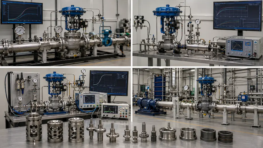
Three Project Scenarios
SCENARIO A · STEAM LOAD SWING
One Steam Valve Must Serve Startup and Full Production
A high maximum steam demand can force selection of a large trim, while startup demand may be only a small fraction of full load. The audit should compare minimum controllable flow, steam pressure ratio, noise, travel, seat behavior and whether a startup bypass, reduced trim or parallel valve arrangement is more reliable than one oversized valve.
SCENARIO B · BATCH CHEMICAL DOSING
Low-Flow Accuracy Matters More Than Peak Capacity
The critical boundary may be the minimum repeatable dose rather than maximum flow. Review trim scale, actuator and positioner resolution, packing friction, flowmeter range, liquid properties and the risk of crystallization or plugging. A micro-flow or specially characterized trim may be required.
SCENARIO C · COOLING WATER SYSTEM
System Pressure Distribution Changes with Load
The valve may have enough inherent rangeability but poor installed behavior because pump head, branch resistance and equipment pressure loss change as other users open and close. The solution may require a different characteristic, improved valve authority, system balancing or revised control architecture rather than a higher catalogue ratio.
Five Selection Shortcuts to Reject
| Shortcut | Why It Fails | Required Proof |
|---|---|---|
| “The process needs 20:1, so a 50:1 valve is automatically acceptable.” | The two ratios may use different definitions and conditions. | Minimum, normal and maximum installed cases with predicted travel. |
| “A larger valve gives more range.” | Oversizing often reduces usable low-flow travel and increases installed gain. | Sizing review and normal operating travel. |
| “Equal percentage always solves high turndown.” | The installed response still depends on system pressure losses and valve authority. | Installed characteristic review. |
| “A smart positioner guarantees fine control.” | It cannot remove wrong sizing, seat effects, severe stiction or poor measurement resolution. | Command-to-travel step response and mechanical inspection. |
| “Full travel proves maximum process capacity.” | Available pressure drop, choked flow and line losses may still limit flow. | Hydraulic calculation using actual P1, P2 and fluid data. |
What to Change When One Valve Cannot Cover the Required Envelope
Reduce the Installed Capacity
Use reduced trim, a smaller body where mechanically suitable, or a lower-capacity characterized element so normal operation moves away from the seat.
Change the Valve Architecture
Consider a globe, angle, segmented-ball, eccentric-plug or micro-flow design better matched to the required fluid, capacity and control behavior.
Split the Operating Range
Use parallel small and large valves, a startup bypass or a staged arrangement where one valve cannot provide acceptable control across the complete demand range.
Change the System
Improve valve authority, revise pressure-drop allocation, change pump control, relocate measurement or correct interacting process constraints.
The complete body, trim and actuator decision path is covered in the Control Valve Selection Guide.
PROJECT DATA GATE
Information Required to Verify the Operating Envelope
Process Cases
Minimum, normal and maximum flow with P1, P2, temperature and fluid properties for each case.
Control Requirement
Required turndown, allowable control deviation, response requirement and critical minimum-flow duty.
Valve Package
Body style, trim, characteristic, rated Cv/Kv, actuator, positioner, fail action and supply conditions.
System Behavior
Pump or compressor curve, fixed and variable pressure losses, downstream pressure changes and parallel users.
Ask the supplier to return predicted Cv/Kv and travel at every operating case, the stated basis for rangeability, any minimum controllable travel limitation and recommended alternatives if one valve cannot cover the required envelope.
Related Technical Resources
Technical References
Frequently Asked Questions
What is control valve rangeability?
Control valve rangeability normally describes the range over which a valve follows a stated flow characteristic within defined limits. Inherent rangeability is associated with controlled test conditions; installed controllability also depends on the process system, actuator, positioner and measurement.
What is process turndown?
Process turndown is the ratio between the required maximum and minimum operating flow. For example, a process that must operate from 100 units down to 5 units has a required turndown of 20:1.
Does a valve with 50:1 rangeability guarantee 50:1 process turndown?
No. The installed controllable range can be reduced by valve oversizing, changing pressure drop, friction, deadband, actuator resolution, measurement limits, leakage, severe-service effects and process instability.
How does oversizing reduce usable range?
An oversized valve may pass minimum and normal flow at very low travel. Small changes near the seat can then create large flow changes, while friction, leakage and seat effects consume part of the available control range.
Is equal-percentage trim always best for high turndown?
No. Equal-percentage trim is often useful where valve pressure drop changes with load, but final suitability depends on the installed system characteristic, valve authority, required flow cases, valve style and control-loop behavior.
What data should be requested from the valve supplier?
Request the basis of the stated rangeability, required Cv or Kv and predicted travel at minimum, normal and maximum flow, the assumed valve pressure drop, inherent characteristic, actuator and positioner configuration, and any minimum controllable-travel limitation.