High-pressure and high-temperature steam control valves should be selected from the actual steam condition and operating cases, not from pipe size alone. The engineering review should include saturated or superheated steam condition, minimum/normal/maximum mass flow, inlet and outlet pressure, operating and design temperature, required Cv or Kv, predicted travel, pressure ratio, choked-flow risk, aerodynamic noise, outlet velocity, body and trim materials, packing and bonnet configuration, actuator force, fail action, leakage requirement, and inspection scope. Severe pressure letdown may require staged or low-noise trim, but the final trim must be confirmed by sizing and project data rather than by generic pressure-class rules.
Power & Steam Engineering Report
Steam Control Valve Selection for High-Pressure and High-Temperature Service
A steam valve can be correctly sized for maximum flow and still be a poor control valve. The engineering task is to prove that one valve package can handle startup, normal load, peak demand, pressure letdown, thermal exposure and acceptable acoustic performance across the actual operating envelope.
Steam Service Design Basis
Start with the steam duty, not the valve size. The valve should be selected from the actual process envelope and the project’s control, material and inspection requirements.
| Steam condition | Saturated or superheated steam, inlet temperature, steam quality if relevant, expected downstream condition |
| Operating cases | Minimum, normal and maximum mass flow with P1 and P2 for each case |
| Control objective | Pressure reduction, steam flow control, process steam distribution, turbine auxiliary duty or coordinated temperature control |
| Project constraints | Pressure class, end connection, materials, leakage requirement, fail action, actuator utility, noise criterion, inspection and documentation |
Selection rule: do not approve a steam control valve from nominal line size, pressure class or one design point alone.
Operating Conditions and Steam State
Saturated Steam
Saturated steam is at its saturation condition for the stated pressure. The project should confirm the actual upstream condition and whether condensate can enter the control station during startup, low load or inadequate drainage.
When dry saturated steam is throttled to a lower pressure, the downstream state does not necessarily remain saturated. The pressure reduction can leave the steam superheated, so downstream density, specific volume and velocity should be based on the calculated downstream condition rather than on an assumption that the outlet is still dry saturated steam.
Superheated Steam
Superheated steam operates above the saturation temperature corresponding to its pressure. In addition to flow capacity, elevated temperature affects body material, trim material, packing, gasket or bonnet configuration, actuator exposure and the surrounding piping design.
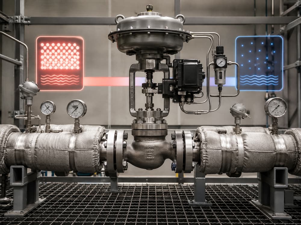
Datasheet Inputs
- Steam type and condition
- Minimum, normal and maximum mass flow
- Inlet pressure for each case
- Outlet pressure for each case
- Operating and design temperature
- Specified noise criterion, if any
- Downstream pipe size and configuration
Minimum, Normal and Maximum Load Review
MINIMUM LOAD
Can the valve control small flow changes?
Check required Cv/Kv, predicted travel, seat influence, leakage effect, positioner resolution, stiction, deadband and minimum stable process demand.
NORMAL LOAD
Will the valve spend most of its life in a useful travel region?
Review normal predicted travel, installed flow characteristic, available pressure drop, aerodynamic noise, outlet velocity and expected continuous operating duration.
MAXIMUM LOAD
Can the valve pass peak demand without entering an unacceptable condition?
Review maximum required Cv/Kv, maximum predicted travel, pressure ratio, choked-flow condition, actuator force, noise and downstream piping impact.
For the detailed sizing workflow, use How to Size a Control Valve. Steam service should use an applicable compressible-fluid sizing method rather than a liquid-service approximation.
Pressure Letdown Review
Choked Flow
Steam control valve sizing should not be reduced to one universal critical pressure ratio. The exact choked-flow condition depends on valve geometry and the applicable compressible-fluid sizing method.
Aerodynamic Noise
High-energy steam expansion and turbulence can generate significant noise. The project should define the required prediction method and acceptance criterion.
Outlet Velocity
The valve outlet and downstream line should be checked using the calculated downstream steam condition. Do not apply one manufacturer’s velocity recommendation as a universal limit.
Erosion and Vibration
Wet steam, condensate carryover, high local velocity, unstable jets or unsuitable trim can accelerate wear and vibration.
IEC 60534-2-1 provides equations for predicting flow through control valves under installed conditions. Where acoustic performance is part of the specification, IEC 60534-8-3 provides a method for predicting aerodynamic noise from compressible-fluid flow.
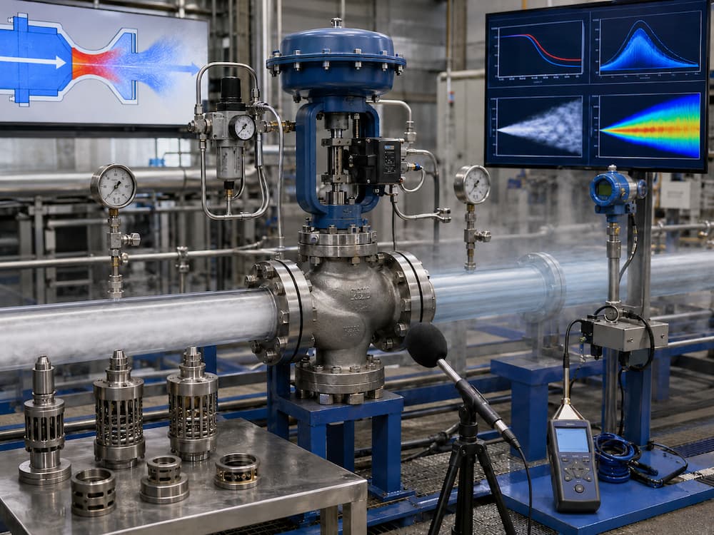
Trim Selection Path
Do not select severe-service trim from pressure class alone. A Class 900, 1500 or 2500 valve does not automatically require multi-stage or low-noise trim. The decision comes from actual flow cases, pressure ratio, noise prediction, velocity, required travel and valve geometry.
For the wider severe-service trim discussion, use Control Valve Trim Options for Cavitation and Noise Reduction.
High-Temperature Construction Review
Body & Bonnet
The selected material and design must satisfy the applicable pressure-temperature rating and project specification. Elevated-temperature steam may require alloy steel or another project-specified material, but no single body material is correct for every steam application.
Trim & Seat
Plug, cage, seat and stem materials should be reviewed for strength, erosion, galling, thermal expansion, leakage requirement and required service life.
Packing & Gasket
Packing and gasket materials must match the actual design conditions and valve construction.
Bonnet Arrangement & Accessories
An extended bonnet may be used on selected designs to increase thermal distance between the hot body and packing or actuator components, but it is not mandatory for every steam control valve. Positioners, solenoids, air sets and electrical accessories should be selected for actual ambient and radiant heat exposure.
For broader material and pressure-temperature selection, review High Temperature High Pressure Valves Guide.
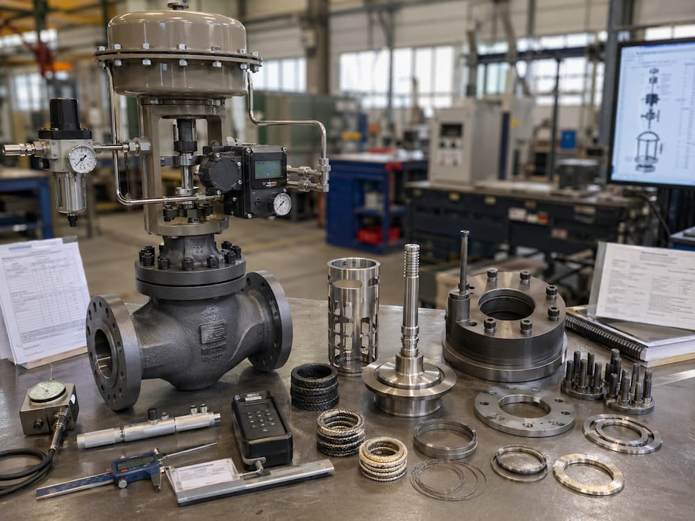
Actuator and Failure Response
| Normal modulation | The actuator must position the valve smoothly across the required operating travel. |
| Shutoff differential pressure | Available thrust or torque must be checked against the specified shutoff condition and selected trim design. |
| Fail action | Fail-open, fail-close, fail-in-place or another response should come from the process safety and control philosophy. Steam service alone does not determine the fail position. |
| Thermal exposure | Actuator seals, positioners and accessories should remain within their approved environmental limits at the final installation. |
Use the Valve Actuator Selection Guide for the wider actuator package review.
Application Cases
CASE A
Steam Header Pressure Reduction
Review full inlet-pressure range, required downstream pressure, minimum and maximum steam demand, choked-flow condition, noise, outlet velocity and downstream piping. For simple local pressure reduction, a pressure regulator may also need to be evaluated; an actuated control valve is appropriate where the process requires external control logic or plant automation.
CASE B
Turbine Auxiliary or Bypass Steam
Large load changes, severe pressure reduction, fast response or thermal transients can make this duty highly application-specific. The project should provide transient and control requirements in addition to steady-state conditions.
CASE C
Process Steam Distribution
Verify minimum controllable flow, normal travel, pressure ratio and whether one valve can cover startup and peak production without excessive gain or severe low-travel operation.
CASE D
Steam Pressure Control with Desuperheating or Spray Water
Where steam pressure control is coordinated with spray-water or desuperheating equipment, the steam valve should be reviewed as one element of the complete system. Steam valve sizing alone cannot establish final outlet temperature performance or complete PRDS behavior.
Startup and Condensate Risk
A control station that normally handles dry steam can still experience condensate during startup, shutdown, warm-up, low-load operation or inadequate drainage. Liquid carryover can increase erosion, vibration and water-hammer risk and may damage trim or downstream piping.
System boundary: valve selection does not replace correct steam-line drainage, warm-up procedure, drip-leg design, steam trapping, piping slope, support design or plant operating practice.
For broader system context, see Power & Steam Valve Solutions.
Steam Control Valve RFQ Datasheet
| Service / tag | ____________________________ |
| Steam condition | Saturated / Superheated / Other: ____________ |
| Minimum case | Flow ______ P1 ______ P2 ______ T ______ |
| Normal case | Flow ______ P1 ______ P2 ______ T ______ |
| Maximum case | Flow ______ P1 ______ P2 ______ T ______ |
| Design pressure / temperature | ____________________________ |
| Line size / connection | ____________________________ |
| Leakage requirement | ____________________________ |
| Actuator / signal / fail action | ____________________________ |
| Noise / inspection / documentation | ____________________________ |
Where process data are complete, request the supplier to return calculated Cv/Kv, predicted travel for minimum/normal/maximum flow, selected trim basis, actuator sizing basis, noise review where required and any stated operating limitation before final approval.
Factory Verification
| Item | Typical Status | Purpose |
|---|---|---|
| Material records | If specified | Confirm specified pressure-containing, trim or bolting materials |
| Dimensional inspection | Required for approved package | Check connection, face-to-face and actuator arrangement |
| Pressure test | Per applicable standard / PO | Verify pressure-containing integrity |
| Seat leakage test | If leakage requirement applies | Verify specified seat leakage performance |
| Stroke / fail-action test | For actuated package | Check travel, actuator operation and specified failure response |
| Final packing inspection | Before shipment | Protect valve, ends, actuator, positioner and tubing |
For a product-level high-pressure modulation option, review the High Pressure Control Valve. For the complete product family, visit the Control Valve category.
Related Technical Resources
Technical References
Frequently Asked Questions
What data are required to size a steam control valve?
Provide minimum, normal and maximum steam flow, inlet and outlet pressure for each case, steam condition, operating and design temperature, line size, required control function and project constraints. The supplier should calculate Cv or Kv and predicted travel using an applicable compressible-fluid sizing method.
Can a steam control valve be selected by pipe size?
No. Pipe size is only one project input. Final valve size and trim depend on steam flow, pressure ratio, temperature, required Cv or Kv, predicted travel, noise, velocity, actuator force and the full operating envelope.
When is low-noise trim required for steam?
Low-noise or staged trim should be considered when predicted aerodynamic noise or pressure-letdown severity exceeds the project acceptance criteria. The selection should be based on actual sizing and noise review rather than pressure class alone.
What is choked flow in a steam control valve?
Choked flow is a compressible-flow condition in which valve mass-flow capacity becomes limited by the pressure ratio and valve characteristics. The exact condition should be determined using the applicable control valve sizing method.
Does dry saturated steam remain saturated after pressure reduction?
Not necessarily. Throttling dry saturated steam to a lower pressure can produce a superheated downstream state. The downstream condition should be calculated so that specific volume, velocity and related sizing checks use the correct steam properties.
Is fail-close always required for a steam control valve?
No. Fail-open, fail-close, fail-in-place or another defined failure response depends on the process safety and control philosophy.