A turbine bypass valve is a severe-service steam control valve used to route steam around the turbine during startup, shutdown, trip or selected load-management conditions. It may be required to reduce very high steam pressure, control rapidly changing steam flow and coordinate with desuperheating so the downstream reheater, cold-reheat line, condenser path or other receiving system is protected. Correct selection requires minimum/normal/maximum and transient steam flow, upstream and downstream pressure, steam temperature, required opening time, actuator dynamics, noise limits, outlet velocity, trim design, spray-water conditions, downstream equipment limits and the complete plant bypass philosophy.
Power & Steam · Severe-Service Bypass Duty Review
Turbine Bypass Valve Selection for Power Plants
Turbine bypass service is not simply “another steam pressure-reducing valve.” The valve may need to accept a sudden change in steam flow, reduce a very large pressure ratio, manage aerodynamic noise and coordinate with spray-water desuperheating while protecting the downstream steam system.
Where the Turbine Bypass Valve Fits
The exact arrangement depends on plant architecture. The functional map below shows typical bypass logic only and should not be treated as a universal P&ID.
High P / High T
Severe pressure reduction
Why Turbine Bypass Is More Severe Than General Steam Letdown
Large Pressure Ratio
Steam can enter at main or reheat steam conditions and discharge to a much lower-pressure system. The valve may therefore require staged pressure reduction rather than one uncontrolled expansion.
Fast Transients
Trip, startup and shutdown duties may require rapid movement and stable control while steam conditions are changing quickly.
Downstream Protection
The receiving system can impose limits on pressure, temperature, noise, velocity, thermal shock and steam quality that the bypass station must respect.
A valve suitable for normal process steam pressure reduction should not automatically be assumed suitable for turbine bypass duty.
HP Bypass and LP Bypass Are Different Duties
| Duty | Typical Functional Direction | Main Selection Concern |
|---|---|---|
| HP Bypass | Routes high-pressure main steam around the HP turbine toward cold-reheat or another approved downstream steam path. | Very high inlet pressure, pressure ratio, trim energy management, desuperheating and downstream reheater protection. |
| LP / Reheat Bypass | Routes reheat steam around the downstream turbine section toward a still lower-pressure receiving system or condenser path. | Large flow, downstream pressure limit, outlet velocity, noise, desuperheating and condenser / piping protection. |
The names HP and LP bypass describe plant function, not one universal valve construction. Final valve geometry must follow the actual steam conditions and plant scheme.
SEVERE-SERVICE REVIEW A
Multi-Stage Pressure Reduction and Trim Design
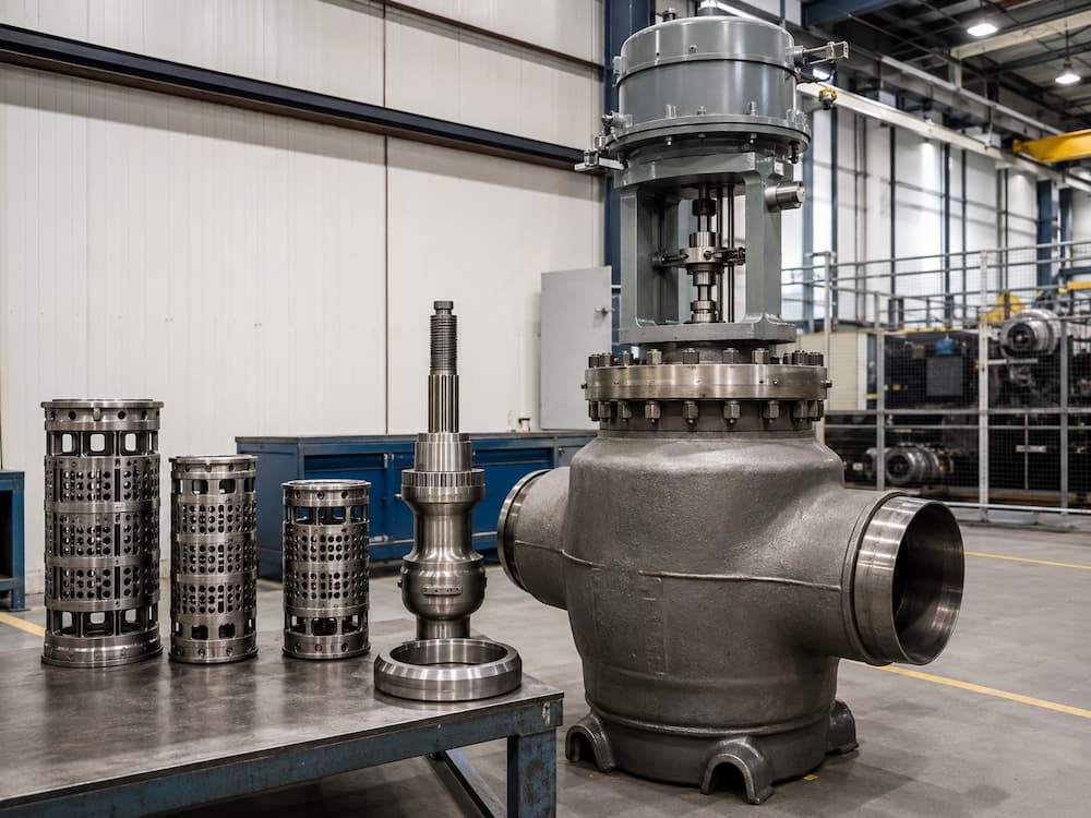
A very large steam pressure drop can drive choking, high local velocity, aerodynamic noise, vibration and trim erosion. Severe-service turbine bypass valves may therefore use staged expansion, drilled cages, multi-path trim or another order-specific pressure-reduction architecture.
Single severe expansion
Staged expansion
Outlet management
Do not specify “multi-stage trim” only because the valve is Class 1500 or Class 2500. The required trim architecture should come from actual P1/P2, steam flow, temperature, valve geometry and acoustic/mechanical analysis.
SEVERE-SERVICE REVIEW B
Actuator Dynamics and Required Opening Time
In turbine bypass duty, actuator sizing is not only a static force calculation. The system may specify a required opening time after a turbine trip or during startup sequencing. The actuator must deliver the required travel under real steam forces and available supply conditions.
| Required opening time | Must come from the plant bypass philosophy or turbine/boiler protection study. |
| Available air / hydraulic pressure | Determines available actuator force and transient capability. |
| Fail action | Must follow approved protection logic; do not assume fail-open or fail-close universally. |
| Dynamic steam load | Trim pressure balance and steam forces affect actuator thrust. |
SEVERE-SERVICE REVIEW C
Desuperheating Must Follow the Bypass Transient
Pressure reduction alone may still leave steam too hot for the receiving system. Turbine bypass therefore often works together with integrated or downstream desuperheating. The water system must respond quickly enough to match changing steam mass flow without over-spraying at low load or under-cooling during large bypass events.
Steam-Side Requirements
- Transient steam flow range
- P1 and required P2
- Inlet steam temperature
- Required outlet temperature
- Maximum downstream equipment temperature
Water-Side Requirements
- Available spray-water pressure
- Water temperature
- Minimum / maximum water flow
- Nozzle / desuperheater design
- Required response and mixing distance
For the general pressure-and-temperature control relationship, see Steam PRDS Valve Selection. For water-side selection, see Spray Water Control Valve.
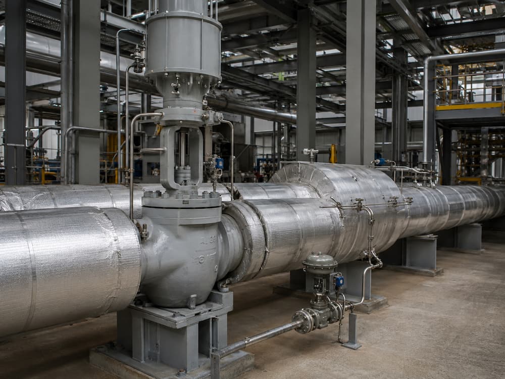
Startup, Controlled Bypass and Turbine Trip Are Different Cases
| Case | Possible Valve Challenge | Data Needed |
|---|---|---|
| Startup | Low or changing flow, large ΔP, low-travel controllability and unstable spray demand. | Startup flow sequence, P1/P2/T, pressure ramp and outlet-temperature target. |
| Controlled bypass | Stable modulation, noise, outlet velocity and desuperheating range. | Min/normal/max flow and expected duration. |
| Turbine trip | Rapid opening, sudden high flow and transient pressure/temperature control. | Trip flow, opening time, upstream transient, downstream pressure limit and spray response. |
One steady-state design point is not enough. Turbine bypass selection should include the transient cases that govern actuator, trim and desuperheating performance.
Noise, Outlet Velocity and Downstream Piping
Large steam pressure drops can move acoustic and kinetic energy downstream of the valve. Noise therefore cannot be treated as a valve-only issue. Outlet piping, reducers, diffusers, elbows, supports and downstream equipment all participate in the mechanical response.
- Review predicted valve noise for governing flow cases.
- Check steam outlet velocity and pipe-size transition.
- Review piping support and vibration loads.
- Check desuperheating mixing distance and sensor location.
- Confirm the downstream system can accept bypass mass flow and thermal load.
No universal maximum steam velocity should be copied into every turbine-bypass specification. The project and system analysis should establish acceptable limits.
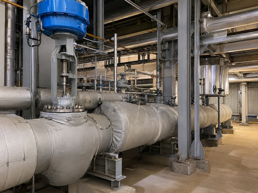
Valve Construction Review
Body / Pressure Boundary
Confirm design pressure and temperature, material, pressure-temperature rating, end connection and any pressure-seal or welded construction requirement.
Trim
Review pressure balance, staged pressure reduction, seat loading, hardfacing, erosion resistance and replaceability where required.
Bonnet / Packing
Check temperature capability, packing load, live-loading if specified and long-term stem sealing.
Actuator / Controls
Confirm thrust, travel, stroking time, fail function, instrumentation and plant trip-interface requirements.
Existing Vcore pages that can support component-level review include High Pressure Control Valve, Steam Control Valve and Spray Water Control Valve. Final turbine-bypass suitability must still be confirmed against the project-specific duty.
Turbine Bypass Valve RFQ Data
Steam Conditions
- Minimum / normal / maximum bypass flow
- Trip / transient flow if applicable
- Upstream pressure and temperature for each case
- Required downstream pressure
- Required downstream temperature
- Design pressure and temperature
Dynamic Requirements
- Required opening / closing time
- Fail action
- Actuator type / utility supply
- Expected cycling frequency
- Normal bypass duration
- Turbine-trip operating sequence
Desuperheating Data
- Spray-water pressure
- Spray-water temperature
- Available water flow
- Integrated or separate desuperheater preference
- Available mixing distance
Piping / Project Limits
- Upstream and downstream pipe size
- Downstream system / equipment
- Maximum noise requirement
- Material / standard requirements
- NDE / testing / documentation
- OEM / EPC bypass specification
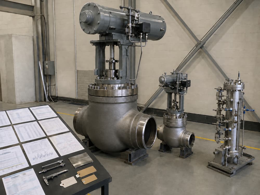
Factory Verification vs Site Performance
| Verification | Scope |
|---|---|
| Valve sizing / trim review | Confirm stated flow and pressure-drop cases. |
| Actuator sizing / travel test | Verify force and movement under agreed factory conditions. |
| Pressure / seat testing | Verify pressure-boundary and shut-off performance to the purchase specification. |
| Material / NDE records | As required by the project and selected construction. |
| Noise / transient validation | May require project/OEM analysis beyond ordinary factory valve testing. |
| Integrated bypass commissioning | Site-level verification of pressure, temperature, actuator response and spray-water coordination. |
Factory acceptance of the valve does not by itself prove that the complete turbine-bypass system will meet site transient, noise and outlet-temperature requirements. Those also depend on installed piping, desuperheating, instrumentation, control logic and commissioning.
Related Technical Resources
Technical References
Frequently Asked Questions
What is a turbine bypass valve?
A turbine bypass valve is a severe-service steam control valve used to route steam around a steam turbine during startup, shutdown, trip or selected load-management conditions while controlling downstream pressure and coordinating with desuperheating where required.
Is a turbine bypass valve the same as a normal steam pressure reducing valve?
No. Turbine bypass service can involve much larger pressure ratios, rapid transients, strict opening-time requirements, high noise and dynamic coordination with a desuperheating system.
Why do turbine bypass valves use multi-stage trim?
Multi-stage or other severe-service trim can divide a large steam pressure reduction into controlled steps to manage local velocity, acoustic energy and mechanical loading. It is selected from actual flow and pressure conditions rather than pressure class alone.
Does every turbine bypass valve include desuperheating?
Not every valve integrates water injection in the same body, but turbine bypass systems commonly require steam temperature control. Desuperheating may be integrated or installed separately downstream.
What is the difference between HP and LP turbine bypass?
HP bypass generally routes main steam around the high-pressure turbine toward a lower-pressure steam path such as cold reheat. LP or reheat bypass routes downstream turbine steam toward a still lower-pressure receiving system or condenser path. Actual architecture varies by plant.
How fast should a turbine bypass valve open?
There is no universal opening time. The requirement should come from the turbine, boiler or plant protection study and be checked together with actuator force, utility supply, valve travel and steam dynamics.
What data are needed to quote a turbine bypass valve?
Provide minimum, normal, maximum and trip steam flow; inlet and outlet pressure; inlet and required outlet temperature; design pressure and temperature; required opening time; actuator/fail requirements; spray-water conditions; downstream system limits; noise requirement; line sizes; materials and project specification.