Industrial Valve Design Considerations: 10 Engineering Factors for Reliable Valve Selection and Customization
Industrial valve design is not simply the process of choosing a body shape and assigning a pressure class. A valve must convert process conditions into a pressure boundary, flow path, sealing system, operating mechanism and inspection plan that can work together under real service conditions.
This becomes especially important when a project involves high pressure, high temperature, corrosive media, abrasive solids, frequent cycling, tight shutoff, automation, fugitive-emission control, unusual dimensions or project-specific documentation. In these services, a catalog description such as “4 in, Class 300, carbon steel ball valve” is not enough to approve the design.
This guide explains the main industrial valve design considerations that engineers, EPC contractors, distributors and procurement teams should review before approving a standard valve, a modified catalog valve or a project-specific configuration. The objective is not to prescribe one universal design, but to show how service data, materials, sealing, pressure-temperature rating, actuation, interfaces and verification should be connected.
Quick Summary
- Start with the actual process duty: medium, design pressure, design temperature, differential pressure, flow behavior, cycling and failure consequence.
- Select the valve type and internal architecture from the required function, not from line size alone.
- Pressure boundary materials, trim, seats, packing, gaskets and bolting must be reviewed as one temperature- and media-compatible system.
- Valve design must also confirm torque or thrust, fail action, end connections, face-to-face dimensions, installation orientation and maintenance access.
- Testing, inspection and documentation should be defined before purchase so the delivered valve can be verified against the approved design basis.
What Does Industrial Valve Design Actually Include?
For project procurement, “valve design” can mean several different things. It may refer to selecting a proven standard valve, modifying a standard configuration, or developing a special construction for a service that cannot be met by an existing product family.
| Design Level | Typical Scope | When It Is Used | Main Approval Focus |
|---|---|---|---|
| Standard catalog configuration | Existing valve type, body, trim, seat and operator options | Normal industrial service within established product limits | Correct selection and compliance with datasheet |
| Configured / modified valve | Special material, seat, packing, coating, actuator, stem extension, end connection or testing | Project requirements differ from the normal catalog configuration | Compatibility of modified components with the base design |
| Project-specific engineering | Special geometry, pressure boundary, trim, flow path or structural arrangement | Unusual dimensions, severe service or performance requirements | Engineering calculations, drawings, qualification and testing |
A project does not automatically need a completely new valve simply because it has a special requirement. In many cases, the safest and most economical solution is a proven valve platform with carefully controlled materials, trim, seats, actuation and testing. A new or heavily modified design should be justified by the service requirement rather than by the word “custom.”
1. Define the Process Duty Before Selecting the Valve
The first design gate is the service condition. Without reliable process data, downstream design choices become assumptions. The valve supplier should understand not only nominal pressure and temperature, but also the conditions that control mechanical loading, sealing and wear.
| Required Service Data | Why It Matters to Valve Design |
|---|---|
| Fluid / gas composition | Controls corrosion, compatibility, emissions risk, solids behavior and cleaning requirements. |
| Design pressure and temperature | Establishes pressure-boundary rating and material limits. |
| Normal operating pressure and temperature | Shows the real duty that seats, packing and trim will experience most of the time. |
| Maximum differential pressure | Affects seat loading, operating torque or thrust, trim force and actuator sizing. |
| Flow rate / velocity | Important for pressure loss, erosion, cavitation, noise, check-valve stability and control behavior. |
| Solids, viscosity or slurry content | Influences blockage risk, seat cleaning, cavity design, erosion and valve type. |
| Cycle frequency | Determines wear, fatigue, packing life and actuator duty. |
| Required shutoff / leakage level | Defines seat architecture, seating force and test requirement. |
| Fail position and safety function | Controls actuator type, stored energy and accessories. |
| Environment | Ambient temperature, outdoor exposure, vibration, hazardous area and corrosion affect actuator, coating and accessories. |
2. Select the Valve Type and Internal Architecture
The valve type should follow the required function. Isolation, throttling, backflow prevention, pressure reduction and emergency shutdown impose different demands on the closure member, seats, stem, flow path and operator.
| Valve Function | Common Valve Types | Design Questions to Confirm |
|---|---|---|
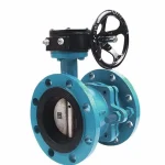
| On-off isolation | Ball, gate, butterfly, plug | Shutoff level, bore, pressure drop, torque, cavity, seat direction and cycling |
| Throttling / control | Globe control, angle control, rotary control | Cv/Kv, travel, pressure drop, cavitation, flashing, noise, trim velocity and leakage class |
| Backflow prevention | Swing, lift, dual-plate, axial / nozzle check | Minimum velocity, orientation, closure dynamics, slam risk and pressure loss |
| High-temperature isolation | Gate, globe, metal-seated ball, pressure-seal designs where applicable | Thermal expansion, body/bonnet joint, packing, hardfacing and operating force |
| Corrosive service | Stainless, alloy, lined or rubber-lined valves | Full wetted material compatibility, permeation, lining support and temperature limit |
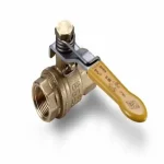
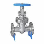
Internal architecture matters as much as the generic valve name. For example, a ball valve may be floating or trunnion mounted, soft seated or metal seated, full bore or reduced bore, top entry or side entry, and may use different seat pressure-relief behavior. A gate valve may use wedge, parallel slide or slab gate construction. A control valve may use balanced or unbalanced trim, cage guidance, multistage pressure reduction or hardened severe-service trim.
For a deeper example of how body style, trim and actuator decisions interact, see the Control Valve Selection Guide.
3. Confirm Pressure-Temperature Rating and Pressure Boundary Design
The valve body is part of the piping pressure boundary. The selected body material, valve class, end connection, wall thickness, bolting and temperature must therefore be consistent with the applicable design standard and project specification.
ASME B16.34 is widely used for flanged, threaded and welding-end valves and addresses areas including pressure-temperature ratings, materials, dimensions, testing and marking for covered valve constructions. However, a pressure class alone does not guarantee that every internal component is suitable for the same temperature.
Seats, O-rings, packing, gaskets, springs, coatings and actuators can impose lower practical temperature limits than the pressure-containing body. The buyer should therefore review the complete pressure-temperature envelope rather than reading only the body nameplate.
For a detailed procurement workflow, use the Valve Pressure-Temperature Rating Guide.
4. Design the Flow Path for the Actual Hydraulic Duty
The internal flow path controls pressure loss, velocity distribution and the forces acting on the closure member. This is especially important in high-flow, high-pressure-drop, slurry, flashing, cavitating or rapidly cycling service.
Important hydraulic design questions include:
- Is full bore required for pigging, low pressure drop or solids passage?
- Will a reduced bore create unacceptable velocity or pressure loss?
- Does the valve have a preferred flow direction?
- Could the trim experience cavitation, flashing, choking or erosive velocity?
- Can a check valve close quickly enough to control reverse-flow deceleration without excessive slam?
- Will solids collect in a body cavity or behind a seat?
- Does the valve require smooth throttling or only full-open/full-close operation?
For complex flow problems, engineering tools such as Computational Fluid Dynamics may be used by the responsible design organization to investigate local velocity, pressure recovery, recirculation or trim loading. CFD is a design aid, not a substitute for a correct process datasheet, applicable design rules or physical testing when qualification is required.
5. Select Body, Bonnet and Trim Materials as a Complete System
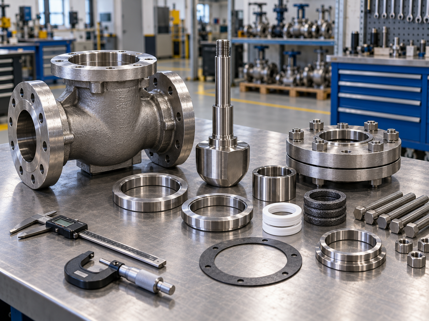
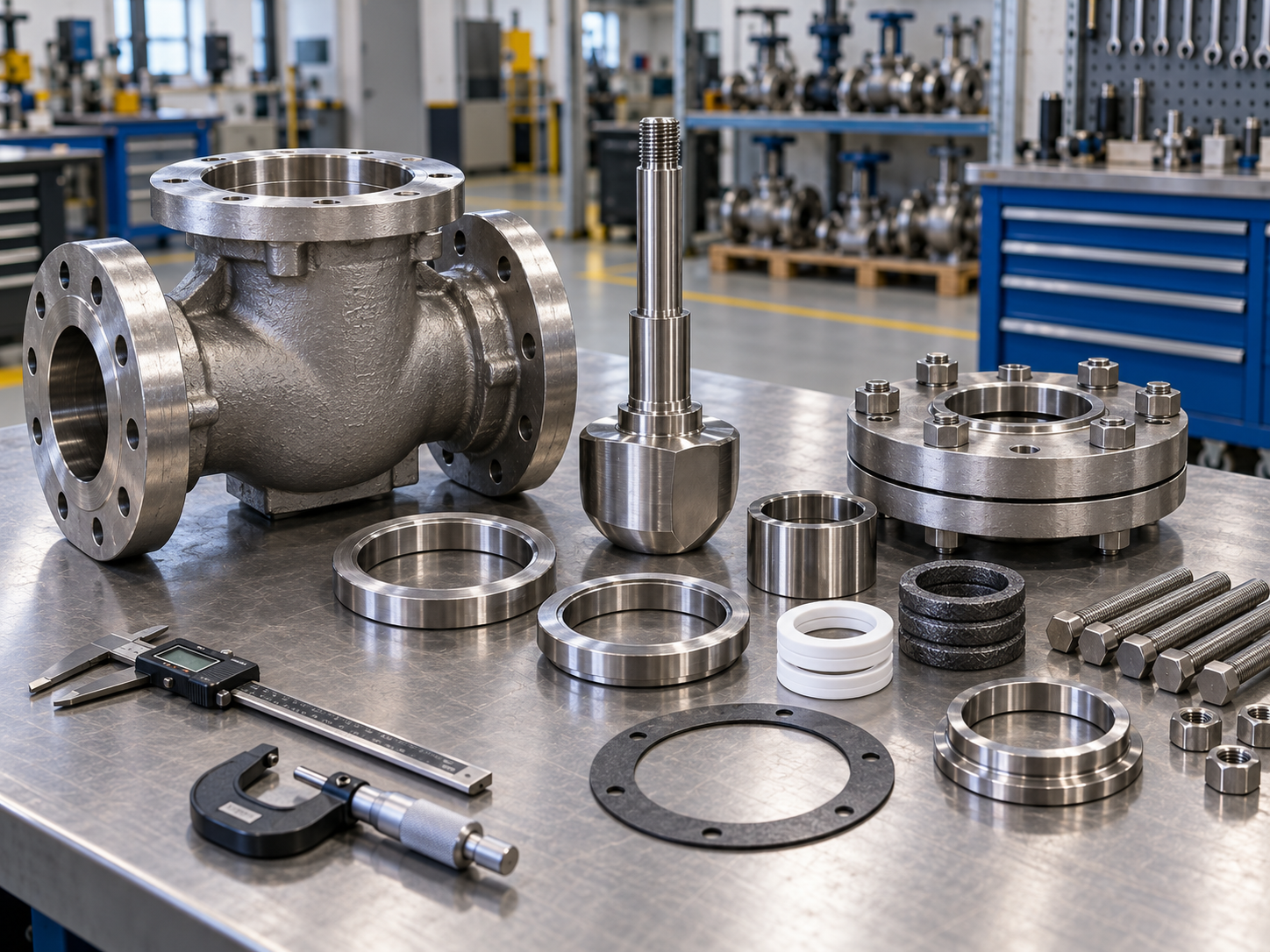
Material selection should be based on mechanical strength, temperature, corrosion mechanism, erosion, galling risk, fabrication requirements and project restrictions. Choosing the body grade alone is not enough because trim components often face higher velocity, sliding contact or concentrated corrosion.
| Component Group | Typical Material Considerations | Failure Risk if Mismatched |
|---|---|---|
| Body / bonnet | Pressure-temperature rating, toughness, corrosion, weldability | Wall loss, cracking, brittle behavior or loss of pressure integrity |
| Closure member | Corrosion, erosion, surface hardness, deformation | Seat damage, leakage, distortion or sticking |
| Stem / shaft | Torsion or thrust, corrosion, galling, fatigue | Twisting, fracture, seizure or packing damage |
| Seat / seat ring | Media compatibility, temperature, contact stress, wear | Leakage, swelling, softening, erosion or cracking |
| Guides / pins / springs | Wear, fatigue, corrosion and small-section strength | Instability, jamming, broken internal parts |
| Bolting | Strength, temperature, corrosion and project specification | Loss of joint preload or body-joint leakage |
Typical body material families include carbon steel, low-temperature carbon steel, stainless steel, alloy steel, duplex grades, nickel alloys, ductile iron and lined constructions. The exact grade should be selected from service chemistry and the applicable project standard.
For internal component selection, see the Valve Trim Materials Selection Guide.
6. Engineer the Seat and Sealing System
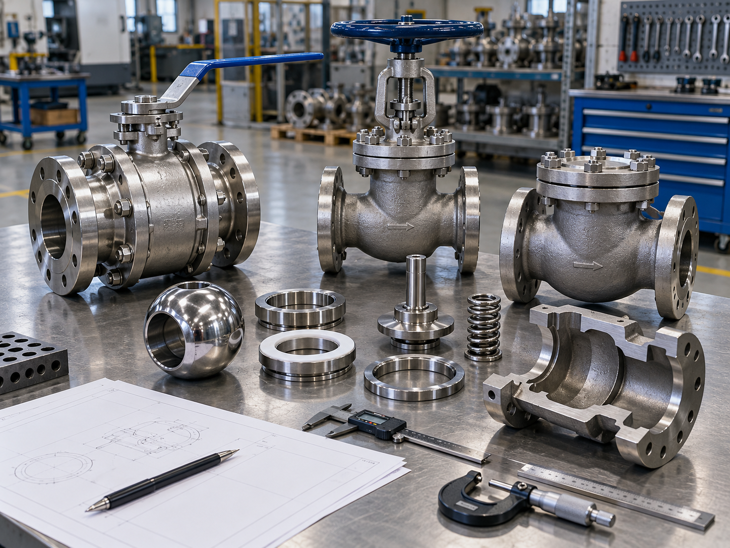
A valve can have an adequate pressure boundary and still fail its primary function if the seat or stem sealing system is wrong. Seat design affects shutoff, operating force, temperature capability, contamination tolerance, wear and maintenance.
Soft Seats
Polymer or elastomer seats can provide tight shutoff in compatible service. Their use depends on pressure, temperature, media chemistry, solids, differential pressure and cycling. PTFE, modified PTFE, PEEK, PCTFE, EPDM, NBR, FKM and other materials each have different application limits.
Metal Seats
Metal seats are selected where temperature, abrasion, erosion or severe service makes a soft seat unsuitable. Hardfacing or coatings may improve wear resistance, but surface material alone does not guarantee tight shutoff. Seat geometry, contact stress, machining, lapping, actuator force and test conditions still control leakage performance.
Stem Packing and Body Joints
Stem or shaft packing must contain the process fluid while allowing movement. Packing friction also affects actuator sizing. Body-bonnet gaskets, body seals and O-rings must remain compatible with temperature, pressure and chemical exposure.
Where fugitive-emission control is part of the project, the buyer should specify the required qualification or production acceptance standard. ISO 15848-1, for example, addresses type testing of external leakage from valve stem or shaft seals and body joints for covered industrial valves.
For more detail, read the Valve Sealing Performance Guide.
7. Calculate Operating Torque, Thrust and Actuator Requirements
A valve that cannot fully open, close or reach the required fail position is not an acceptable design. Manual operators, gearboxes and actuators must be selected from realistic operating loads rather than nominal valve size alone.
Depending on valve type, operating force can be influenced by:
- Maximum differential pressure
- Seat preload and friction
- Packing friction
- Stem, shaft and bearing friction
- Hydrodynamic torque
- Line pressure acting on unbalanced trim
- Temperature and thermal expansion
- Deposits, solids or corrosion products
- Required closing or opening time
- Safety factor required by the project or actuator sizing practice
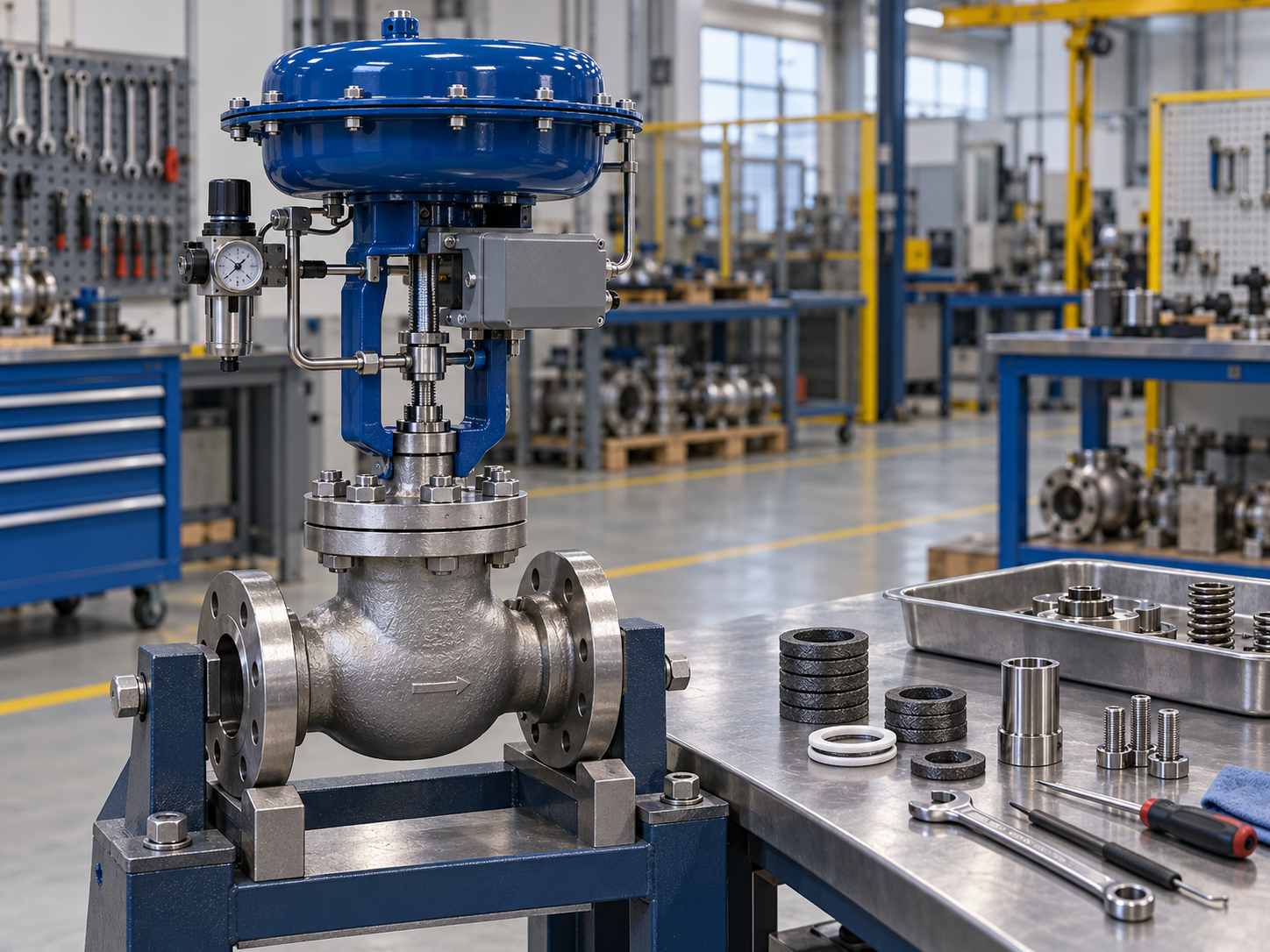
Automated valves also require confirmation of fail-open, fail-closed or fail-in-place behavior; pneumatic supply; electrical power; control signal; hazardous-area classification; limit switches; solenoid valves; positioners; local override and mounting interface.
8. Confirm Dimensions, End Connections and Installation Interfaces
Even a technically capable valve can create site rework if its mechanical interfaces are wrong. The design review should verify how the valve fits the piping system, actuator access and maintenance envelope.
Key interface items include:
- Nominal size and bore
- Flanged, wafer, lug, threaded, socket-weld or butt-weld ends
- Flange facing and pressure class
- Face-to-face or end-to-end dimension
- Butt-weld end preparation and pipe schedule where applicable
- Flow direction
- Installation orientation
- Operator position and clearance
- Stem extension or buried-service extension
- Actuator mounting orientation
- Drain, vent or body-cavity connections
- Maintenance access for seat, packing, trim or actuator removal
ASME B16.10 is one commonly used dimensional standard for face-to-face and end-to-end dimensions of many straightway valves and center-to-face / center-to-end dimensions of angle valves. Project drawings should confirm the actual dimensional series that applies to the selected valve type.
9. Apply the Correct Design, Testing and Service Standards
No single standard covers every industrial valve design. The project may need separate standards for valve construction, dimensions, flange interfaces, pressure testing, fire-safe qualification, fugitive emissions, sour service or a specific valve type.
| Requirement Area | Common Reference | Design Review Use |
|---|---|---|
| General pressure boundary / ratings | ASME B16.34 where applicable | Pressure-temperature rating, materials, construction, testing and marking framework |
| Face-to-face dimensions | ASME B16.10 where applicable | Installation interchangeability and dimensional confirmation |
| Pipeline valves | API 6D where specified | Pipeline valve requirements for covered valve types and service |
| Valve pressure testing | API 598 or project/product-specific standard | Shell and closure test requirements and acceptance basis |
| Fugitive emissions | ISO 15848 series or project-specified requirement | External leakage qualification / production acceptance where required |
| Sour service materials | NACE MR0175 / ISO 15156 when applicable | Material restrictions for H2S-containing oil and gas production environments |
The purchase order should identify the exact applicable standard and edition required by the project. The valve manufacturer should not be expected to infer a specialized qualification requirement after production has started.
For testing scope and terminology, review Valve Pressure Testing: Methods, Standards and Inspection Requirements.
10. Define Verification, Documentation and Manufacturing Controls
Design approval is not complete until the buyer can verify that the manufactured valve matches the approved configuration. Required documents depend on project criticality, but they should be defined during the RFQ or technical clarification stage.
| Verification Item | Typical Evidence | Why It Matters |
|---|---|---|
| Material identity | MTC / MTR, heat number, PMI when specified | Confirms actual pressure-boundary and trim materials |
| Approved construction | Datasheet, GA drawing, BOM or approved technical submittal | Prevents configuration changes between quotation and production |
| Dimensions | Dimensional inspection report | Confirms fit-up and key interfaces |
| Pressure integrity | Shell pressure test record | Verifies pressure-containing boundary under specified test conditions |
| Shutoff | Seat / closure leakage test record | Verifies required sealing performance |
| Actuation | Functional stroke, torque/thrust or actuator setting verification as specified | Confirms the assembled valve package operates correctly |
| Special requirements | NDE, PMI, coating, fire-safe, low-emission, cryogenic or third-party records when required | Verifies project-specific critical features |
For the downstream production sequence, see Industrial Valve Manufacturing: From Casting to Final Testing.
When Does a Project Need a Modified or Custom Valve Design?
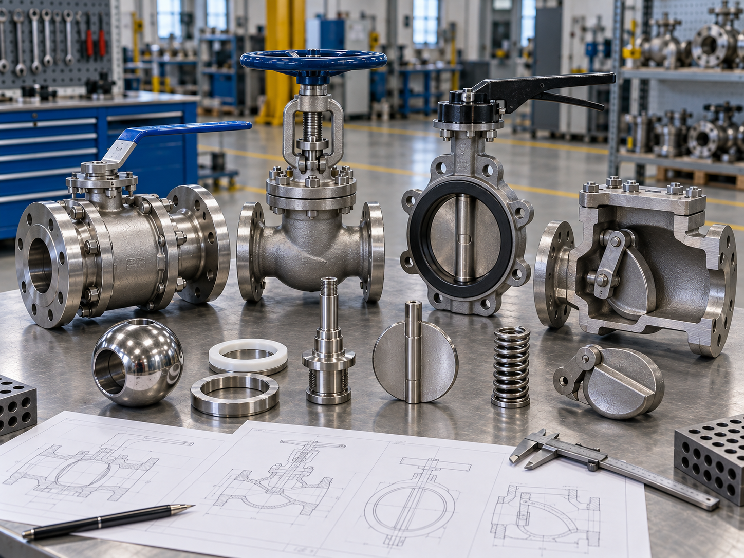
Custom engineering should solve a defined technical problem. It is usually justified when the required service falls outside the normal configuration of a proven product or when the piping system imposes a nonstandard interface.
Typical triggers include:
- Special face-to-face or replacement dimensions
- Unusual bore or flow-path requirement
- High or low temperature beyond standard sealing arrangements
- Very high differential pressure
- Severe corrosion or erosion requiring special wetted materials
- Metal-seat or hardened trim requirements
- Special cavity pressure-relief behavior
- Extended stem or buried installation
- Unusual actuator mounting or fail-safe requirement
- High cycling or accelerated wear concern
- Special fire-safe, low-emission, cryogenic, sour-service or inspection requirements
- Replacement of obsolete equipment where existing piping cannot be modified
For complex modifications, the responsible engineering organization may use CAD modeling, structural calculations, Finite Element Analysis, Computational Fluid Dynamics, prototype testing, cycle testing or other validation methods depending on the design change and project requirement. These methods should be applied where they answer a real design question; they should not be treated as marketing checkboxes.
A Practical Industrial Valve Design Review Workflow
| Gate | Question | Required Output |
|---|---|---|
| 1. Duty | What must the valve do under minimum, normal, maximum and upset conditions? | Confirmed process datasheet |
| 2. Architecture | Which valve type and internal design best match the function? | Valve type and construction |
| 3. Rating | Can the pressure boundary safely cover design pressure and temperature? | Pressure class, material and design basis |
| 4. Materials | Are all wetted and pressure-containing parts compatible? | Body, bonnet, trim, seat, packing, gasket and bolting materials |
| 5. Hydraulics | Are velocity, pressure loss and severe-service effects acceptable? | Bore / trim / flow-path confirmation |
| 6. Sealing | Can the seat, packing and body joints meet leakage requirements? | Seat and sealing configuration |
| 7. Operation | Can the operator deliver required torque/thrust and fail behavior? | Manual / gear / actuator package |
| 8. Interfaces | Will the valve physically fit the piping and maintenance space? | GA drawing and dimensions |
| 9. Standards | Which design, test and special-service standards apply? | Compliance matrix |
| 10. Verification | How will the final valve be inspected and accepted? | ITP / test scope / document list |
Industrial Valve Design RFQ Checklist
A strong RFQ helps the supplier select a proven design or identify whether modification is necessary. For project valves, provide as much of the following information as possible:
| RFQ Item | Information to Provide |
|---|---|
| Valve function | Isolation, throttling, backflow prevention, emergency shutdown, diverting, mixing, etc. |
| Valve type | If specified, identify required type and structure; otherwise allow supplier recommendation. |
| Size and rating | DN/NPS, PN or ASME Class and piping class where applicable. |
| Process conditions | Medium, composition, solids, design pressure/temperature, normal conditions and differential pressure. |
| Materials | Body, trim, seat, lining, packing, gasket and any project material restrictions. |
| Connections | Flanged, wafer, lug, BW, SW, threaded; flange standard, facing and dimensions. |
| Operation | Lever, handwheel, gearbox, pneumatic, electric or hydraulic; fail action and accessories. |
| Leakage | Required seat leakage / shutoff standard and direction where relevant. |
| Standards | Design, dimensions, test, fire-safe, emissions, sour service and project specifications. |
| Inspection | Pressure testing, PMI, NDE, coating, functional tests, third-party inspection. |
| Documents | Datasheet, GA, MTC, test report, certificates, ITP, manuals and spare-parts list. |
Common Valve Design Review Mistakes
Choosing by Size and Class Only
Two valves with the same nominal size and pressure class can require completely different seats, trim, operators and materials because the service duty is different.
Specifying Only the Body Material
Internal trim, stems, seats, springs, packing and gaskets can fail before the body if their materials are not compatible with the process.
Using “Zero Leakage” Without a Test Basis
Shutoff requirements should be connected to a defined test method, pressure, medium, direction and acceptance criterion rather than a generic sales phrase.
Ignoring Differential Pressure in Actuator Sizing
Maximum differential pressure can dominate torque or thrust even when normal line pressure appears moderate.
Adding Special Certifications After the Order
Fire-safe qualification, fugitive-emission qualification, sour-service material restrictions, cryogenic testing and third-party inspection can affect design, materials and production planning. Specify them before manufacturing.
Assuming Custom Always Means Better
A heavily modified valve introduces additional engineering, qualification, spare-parts and schedule considerations. Use a proven standard platform whenever it can meet the service safely and reliably.
FAQ: Industrial Valve Design Considerations
What information is most important before starting an industrial valve design review?
Start with the valve function, medium, design pressure, design temperature, normal operating conditions, maximum differential pressure, flow behavior, required shutoff, cycling frequency, installation details and applicable standards. These inputs control nearly every later material, sealing and actuation decision.
When is a custom valve design necessary?
A custom or modified design may be justified when a standard valve cannot meet required dimensions, materials, pressure-temperature conditions, flow behavior, sealing, actuation, severe-service duty or project qualification requirements. A proven standard design should normally be preferred when it can satisfy the application.
Which standard controls industrial valve design?
There is no single standard for every valve. The applicable standard depends on valve type, service and industry. Projects may combine a construction standard such as ASME B16.34 or an API valve standard with separate dimensional, testing, fire-safe, emissions or material requirements.
How does seat design affect valve performance?
Seat geometry and material influence shutoff, torque or thrust, temperature capability, contamination tolerance and wear. Soft seats can provide very tight shutoff in compatible service, while metal seats are often considered for higher temperature, abrasion or severe service.
Do industrial valve designs always require FEA or CFD?
No. Many standard valves use established design methods, product standards and qualified configurations. FEA, CFD or prototype testing may be useful when a special design change creates structural, hydraulic or performance questions that require additional verification.
What documents should buyers request before approving a project valve?
Depending on project requirements, buyers may request a datasheet, GA drawing, material list, MTC/MTR, pressure test records, dimensional inspection, actuator data, special test certificates, ITP and final documentation package. The required document scope should be agreed before production.
Need to Review a Valve Configuration for Your Project?
Send Vcore Valve your medium, design pressure and temperature, valve size, pressure class, materials, connection, operating method, leakage requirement and applicable project standards. We can help review the required valve configuration and identify the technical information that should be confirmed before quotation and production.
Contact Vcore Valve for project valve selection and RFQ review.