Quick Summary:Industrial valve failure is usually the end result of a mismatch between the valve package and the real service condition, a defect that was not detected before installation, or degradation that was not identified early enough. Common failure modes include internal seat leakage, external stem or body-joint leakage, cavitation and erosion, corrosion, mechanical sticking or component damage, actuator or control loss, check valve instability, and thermal distortion or binding.
Reliable prevention requires more than scheduled maintenance. Valve type, pressure-temperature rating, materials, seat and packing system, flow regime, actuator output, installation orientation, factory testing, traceability and inspection scope should be confirmed before purchase. Once in service, changes in leakage, operating torque, travel time, noise, vibration and position feedback should be treated as diagnostic evidence rather than isolated symptoms.
An industrial valve may pass a factory pressure test and still fail prematurely after installation if the service conditions, valve design, actuator package or operating regime were not correctly defined. Conversely, an older valve can remain reliable for years when the design is suitable, the operating envelope is stable and degradation is detected before it reaches a functional limit.
This guide explains the main industrial valve failure modes from an engineering and maintenance perspective. It focuses on what the operator sees, what may be happening inside the valve, how to investigate the root cause, and what should be changed during specification, purchasing, installation or preventive maintenance to stop the same failure from repeating.
For chemical plants handling aggressive media, lined valves, solvents, acids, alkalis, crystallizing fluids or corrosive slurries, also see Vcore’s Common Valve Failures in Chemical Pipelines. That article addresses chemical compatibility and lining-specific problems in greater detail, while this page covers the wider industrial failure framework.
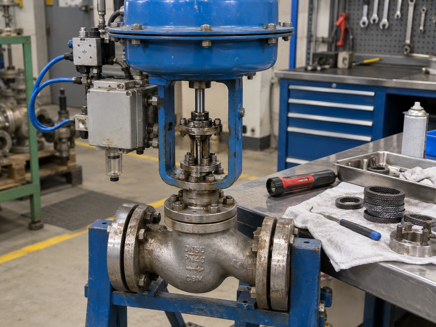
Do not replace a failed valve until the team understands whether the failure came from the valve design, service condition, installation, actuator, control system or maintenance history.
Step 01Define Duty
Identify isolation, throttling, non-return or emergency function and the consequence of failure.
Step 02Match Design
Select the valve type, materials, trim, sealing system and rating for the real service.
Step 03Verify Package
Review dimensions, actuator sizing, tests, inspection records and material traceability.
Step 04Install Correctly
Control alignment, flow direction, support, cleanliness, bolting and commissioning.
Step 05Trend Condition
Use leakage, torque, travel, vibration and inspection history to detect degradation early.
1. What Counts as an Industrial Valve Failure?
A valve has failed when it can no longer perform the function required by the process or safety design. That does not always mean the body has cracked or the valve is completely inoperable. A control valve that moves but cannot stabilize the process, a check valve that chatters and allows damaging reverse flow, or an isolation valve that passes excessive seat leakage may already be functionally failed even though the valve remains physically installed.
| Failure Category | Typical Symptom | Possible Mechanism | First Engineering Check |
|---|---|---|---|
| Internal leakage | Flow continues after closure | Seat wear, contamination, erosion, deformation, incomplete travel | Confirm shutoff requirement, closure travel and seat condition |
| External leakage | Leakage at stem, bonnet, body joint or connection | Packing degradation, gasket failure, stem damage, assembly or bolting problem | Identify the exact leak path before tightening or disassembly |
| Flow-induced damage | Noise, vibration, rapid trim wear, loss of capacity | Cavitation, flashing, erosion, high velocity or solids | Review pressure profile, flow cases and material damage pattern |
| Corrosion / material attack | Pitting, wall loss, rough surfaces, external seepage | Material incompatibility, coating damage, galvanic or environmental attack | Reconfirm medium chemistry, temperature and actual material |
| Mechanical failure | High torque, sticking, incomplete travel, broken component | Deposits, galling, misalignment, stem or shaft damage, excessive load | Separate process resistance from actuator or gearbox problems |
| Actuation / control failure | Valve does not move to commanded position | Insufficient torque or thrust, utility loss, positioner, switch or control fault | Verify valve demand and actuator output at worst utility condition |
| Check valve instability | Chatter, slam, impact noise, reverse flow | Low velocity, pulsation, wrong orientation, unsuitable closure dynamics | Review flow regime and installation rather than only seat condition |
| Thermal / cyclic distortion | Binding, high operating force, leakage after temperature change | Differential expansion, thermal cycling, trapped pressure, distorted seats or gate | Compare cold and hot operating conditions and closure sequence |
2. Internal Seat Leakage: When a Closed Valve Does Not Isolate
Internal leakage occurs when process fluid passes through the closed valve because the closure element and seat cannot achieve the required shutoff. The problem can develop in ball, butterfly, gate, globe, plug and check valves, but the failure mechanism depends heavily on the valve construction and service.
Common Causes of Internal Valve Leakage
- Abrasive particles scratch, cut or erode the sealing surfaces.
- Corrosion or cavitation changes the geometry of the seat or closure member.
- Soft seats swell, harden, creep, extrude or lose elasticity outside their approved service range.
- The valve never reaches its true closed position because of actuator setting, travel stop, stem movement or mechanical interference.
- Thermal distortion changes contact between a metal seat and closure element.
- Gate or isolation valves are repeatedly throttled in a position that concentrates velocity across the seating region.
- Foreign material remains on the seat after flushing, fabrication or maintenance.
How to Diagnose Internal Leakage
Start by confirming whether the observed leakage exceeds the specified acceptance requirement. Do not assume that every valve must provide bubble-tight shutoff. The required seat leakage depends on valve type, seat construction, product standard, control-valve leakage class where applicable and the project specification.
Then verify full closure travel and actuator output before dismantling the valve. If the valve reaches the correct mechanical position but still leaks, inspect the sealing surfaces for directional scratches, particles, erosion, corrosion, indentation, seat movement or local deformation. Damage pattern is often more informative than the leakage rate alone.
Selection Controls
- Match the valve type to isolation or throttling duty.
- Specify the required shutoff or leakage criterion.
- Choose seat and trim materials for temperature, chemistry and solids.
- Review pressure differential at the closed position.
Maintenance Controls
- Trend leakage rather than waiting for complete loss of shutoff.
- Inspect seat and closure surfaces after abnormal debris events.
- Verify actuator stops after overhaul or accessory changes.
- Do not lap, grind or machine seats without checking the design limits.
3. External Leakage: Packing, Stem, Gaskets and Pressure-Boundary Joints
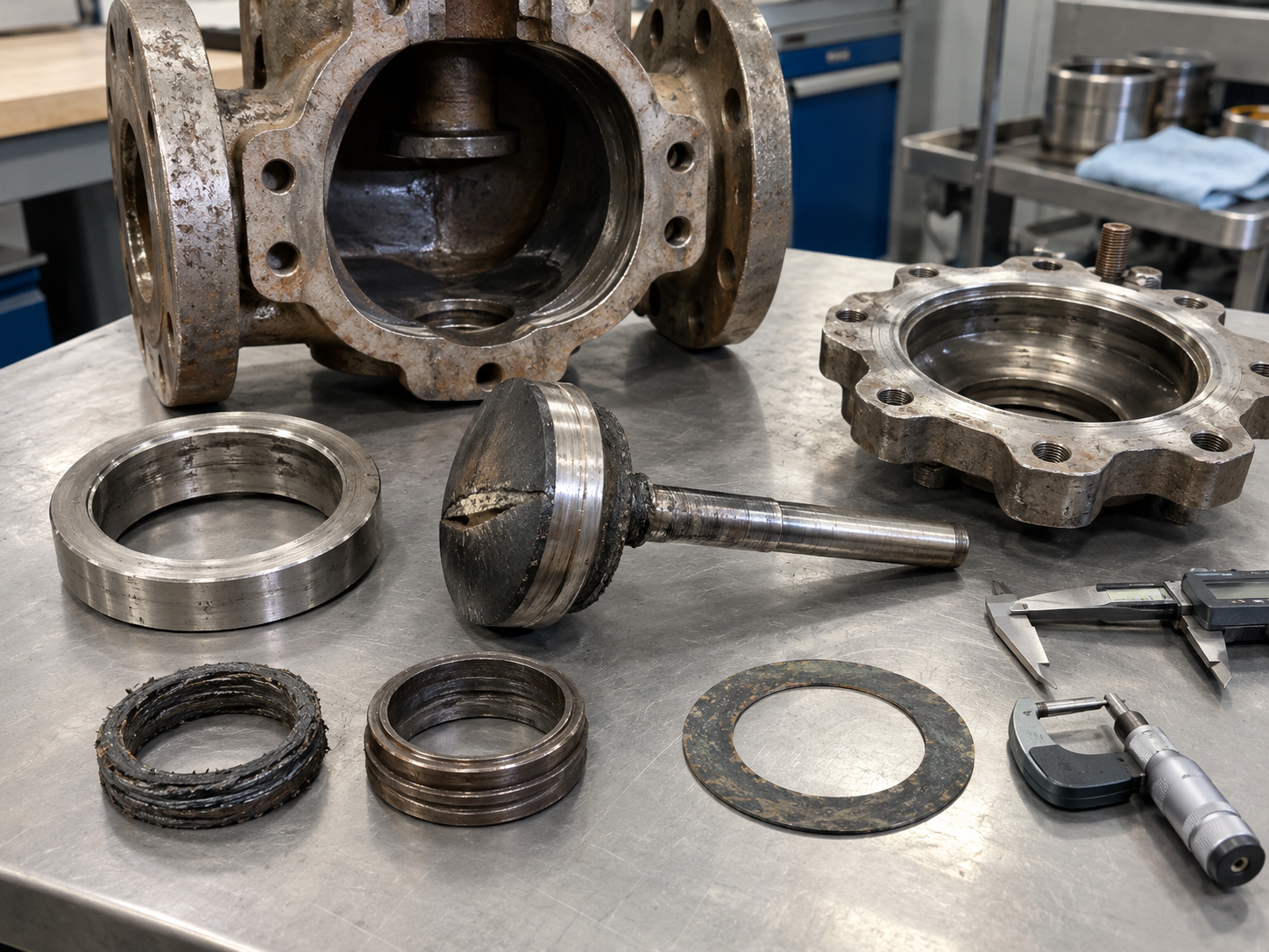
External leakage is fundamentally different from seat leakage because process media escapes from the pressure boundary to the surrounding environment. The exact leak path should be identified before corrective action. Tightening every visible fastener is not a reliable troubleshooting method and can damage packing, gaskets, glands or bolting.
Typical External Leak Paths
- Stem or shaft packing
- Bonnet or cover gasket
- Body joint on multi-piece valves
- Threaded drain, vent or injection connections
- Flanged process connection
- Welded pressure-boundary area
- Body casting, forging or fabricated section if a pressure-boundary defect develops
Stem packing leakage can be caused by unsuitable packing material, incorrect compression, stem scoring, corrosion, excessive cycling, temperature change, poor gland alignment or a packing system that is not suitable for the required emissions performance. For volatile or hazardous service, projects may specify fugitive-emission qualification or production acceptance requirements. Vcore’s Valve Fugitive Emission Testing guide explains the difference between stem emissions, seat leakage and shell leakage and discusses ISO 15848, API 624 and API 641 in their applicable contexts.
4. Cavitation, Flashing, Erosion and Abrasion
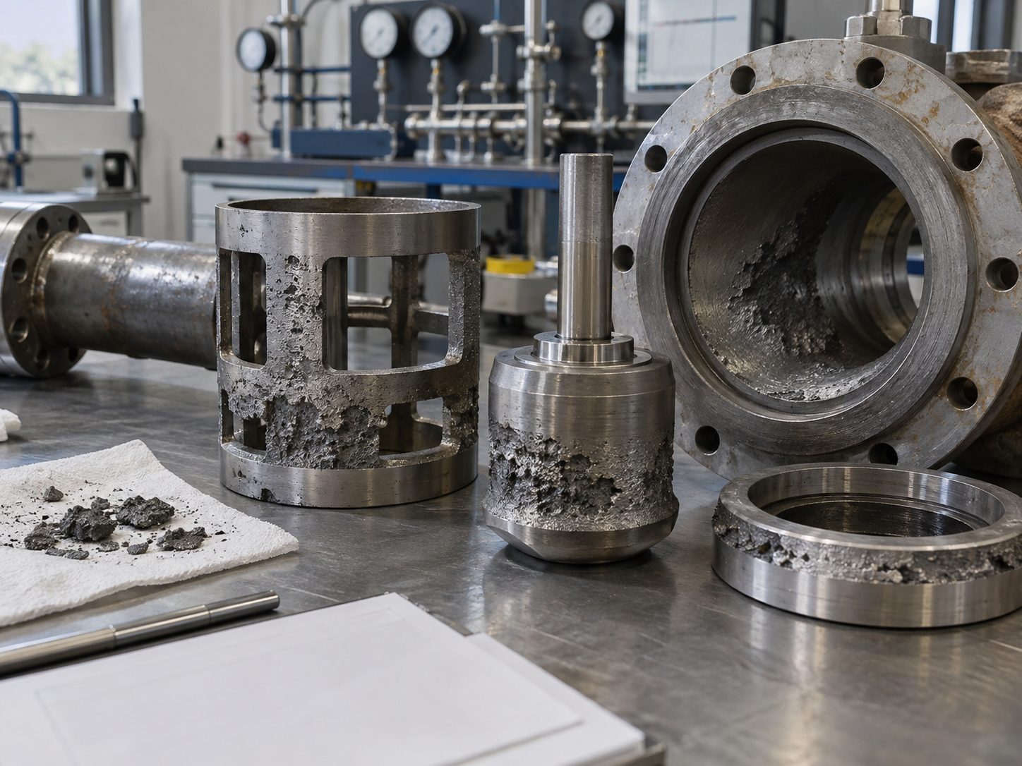
High velocity and severe pressure reduction can destroy valve trim even when the body material is chemically compatible with the fluid. The first step is to distinguish the damage mechanism because cavitation, flashing and solids erosion do not respond to exactly the same corrective action.
Cavitation
In liquid service, cavitation can occur when local pressure falls below the liquid vapor pressure and vapor bubbles later collapse as pressure recovers. The collapse can create intense localized impact on trim and nearby surfaces. Typical evidence includes pitting, roughened surfaces, vibration and characteristic high-frequency noise around the pressure-recovery region.
Control valve sizing should therefore review more than required Cv or Kv. The pressure profile, valve style, pressure-recovery behavior and all operating cases matter. Severe service may require staged pressure reduction, anti-cavitation trim, altered system pressure distribution or another valve configuration. For the broader selection sequence, see the Control Valve Selection Guide.
Flashing
Flashing differs from cavitation because some of the liquid remains vapor after the restriction instead of fully condensing as pressure recovers. Anti-cavitation trim cannot simply eliminate a process condition in which the downstream pressure remains below vapor pressure. Material selection, outlet velocity, erosion resistance and downstream geometry become especially important.
Solids Erosion and Abrasion
Slurries, catalyst particles, mineral solids and dirty services can wear seats, balls, discs, cages, liners and body flow paths. The damage often follows the flow direction and may be concentrated where velocity increases or changes direction. A standard valve selected only from nominal size and pressure class can have a very short life in abrasive service even when it passes every factory pressure test.
5. Corrosion and Material Incompatibility
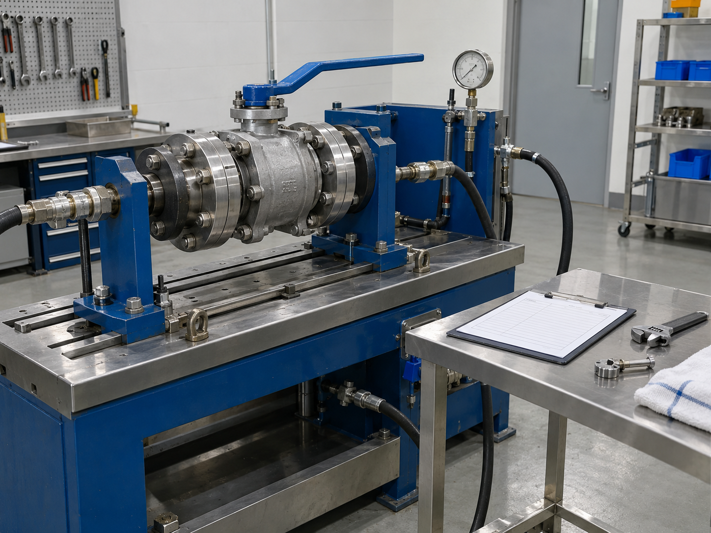
Corrosion failure can affect the pressure boundary, trim, stem, bolting, seat region or external surfaces. A material that is adequate for a clean utility service may be unsuitable when chloride content, chemical concentration, pH, dissolved gases, temperature or cleaning chemicals change.
The failure may appear as uniform wall thinning, localized pitting, crevice attack, galvanic corrosion, coating breakdown or cracking mechanisms that require specialist metallurgical assessment. Because different corrosion mechanisms can look similar during a quick visual inspection, the corrective action should be based on the real medium and damage mechanism rather than the generic instruction to “upgrade to stainless steel.”
Material Verification Before Purchase
- Specify the exact body, bonnet, trim, stem, seat, packing, gasket and bolting materials required by the service.
- Define whether material test reports and heat traceability are required.
- Identify NACE / ISO 15156, hardness, PMI or other project-specific requirements where applicable.
- Review coatings or linings against chemical service, abrasion, temperature, vacuum and handling conditions.
- Do not assume that one stainless steel grade or one elastomer is universally corrosion resistant.
When the application is specifically a chemical pipeline, lining failure, crystallization, seal swelling and aggressive chemical compatibility deserve their own evaluation. Those issues are covered in more depth in Common Valve Failures in Chemical Pipelines.
6. Mechanical Sticking, Excessive Torque and Component Damage
A valve that becomes difficult to operate is sending useful diagnostic information. Rising torque or thrust can come from seat friction, deposits, corrosion, temperature effects, packing compression, damaged guides, stem misalignment, galling, gearbox degradation, process differential pressure or a foreign object in the flow path.
The correct response is to separate the valve’s mechanical demand from the actuator’s available output. Increasing actuator size without checking the valve and stem limits may force a damaged valve through its travel while transferring the overload into the stem, shaft, key, coupling, gearbox or closure element.
| Observed Symptom | Possible Valve-Side Cause | Possible Actuator / Drive Cause | Useful Check |
|---|---|---|---|
| High breakaway torque after long idle period | Seat adhesion, deposits, corrosion, packing friction | Gearbox stiffness or weak actuator output | Compare measured demand with historical torque and actuator data |
| Torque rises through mid-stroke | Foreign object, distorted closure, guide damage, process force | Mechanical misalignment or coupling problem | Inspect travel profile rather than only start/end torque |
| Valve reaches only part of travel | Mechanical stop, jam, thermal distortion | Limit switch, torque switch, positioner or utility limitation | Compare commanded, indicated and actual mechanical position |
| Repeated stem or shaft damage | Excess seating load, misalignment, unsuitable component strength | Actuator oversizing or incorrect torque/thrust setting | Review allowable stem/shaft load and actuator setting |
7. Actuator, Positioner and Control-System Failure
An automated valve can be mechanically healthy and still fail its process function because the actuator, accessories or control system cannot move it to the required position. Pneumatic, electric and hydraulic systems have different failure paths, but all should be evaluated as part of one assembled valve package.
Common Causes
- Pneumatic supply pressure below the value used for actuator sizing
- Restricted tubing, contaminated air, failed solenoid or filter-regulator problems
- Electric power loss, incorrect voltage, motor or control fault, water ingress or duty-cycle mismatch
- Hydraulic pressure loss, leakage, accumulator or control-manifold problems
- Positioner calibration drift, feedback linkage error or incorrect fail action
- Actuator output that no longer exceeds the valve torque or thrust after deposits, corrosion or seat changes
- Incorrect mounting bracket, coupling alignment or travel-stop adjustment
For new equipment, actuator selection should use the valve manufacturer’s verified torque or thrust data and the least favorable utility condition. See the Valve Actuator Selection Guide for pneumatic, electric and hydraulic package selection.
For modulating control valves, positioner setup should be verified as part of the functional test rather than treated as a separate accessory task. Vcore’s Control Valve Positioner Calibration Guide covers zero, span, travel, feedback and fail-action verification.
8. Check Valve Chatter, Slam and Reverse-Flow Damage
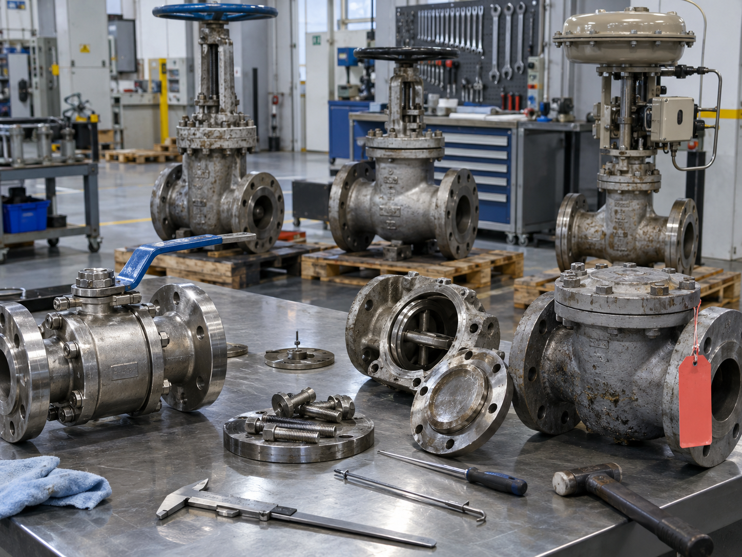
Check valve failures are highly dependent on flow dynamics. A check valve may have a perfect pressure test result and still perform poorly if the disc or plates cannot reach a stable operating position at the real flow rate, if the installation orientation is unsuitable, or if pump trips create rapid reverse velocity.
Typical Warning Signs
- Repeated impact or knocking noise
- Disc or plate chatter during low-flow operation
- Seat wear concentrated by repeated impact
- Broken spring, hinge or stop components
- Reverse flow, pump reverse rotation or surge after shutdown
- Abnormal vibration downstream of the check valve
The corrective action may involve valve type, spring or closure dynamics, installation position, flow velocity, pump operating range, piping layout or surge analysis. Replacing a damaged seat with the same design without reviewing the system can lead to another failure. See the Check Valve Installation Guide for flow direction, horizontal and vertical installation, pump discharge layout and common mistakes.
9. Thermal Distortion, Binding and Temperature Cycling
Temperature changes alter dimensions, clearances, packing friction, seat contact and mechanical loads. In high-temperature steam, hydrocarbon and thermal-fluid systems, a valve can operate normally when cold but become difficult to move or leak after the body, gate, stem and seat regions reach different temperatures.
Gate valves can experience thermal binding when differential expansion or the closing condition creates excessive wedging force. However, the solution is not simply to specify one bonnet type. The review should include the gate and seat geometry, temperature gradient, valve closing sequence, differential pressure, equalization or bypass requirements where applicable, actuator thrust, stem load and the manufacturer’s approved operating procedure.
Repeated thermal cycling can also relax bolted joints, change packing behavior and accelerate damage to soft seats or seals that operate near their temperature limits. A maintenance procedure written only around ambient workshop conditions may therefore miss the conditions that created the field failure.
10. Warning Signs Before an Industrial Valve Failure Becomes a Shutdown
Many failures develop gradually. The most useful inspection program therefore tracks changes from the valve’s normal condition instead of relying only on a generic calendar interval.
Operation
- Higher torque or thrust
- Longer travel time
- Sticking or hesitation
- Unexpected manual effort
Process Behavior
- Unexplained downstream pressure
- Loss of shutoff
- Flow not matching command
- Process oscillation
Condition
- Packing seepage
- Noise or chatter
- Vibration
- Corrosion or coating damage
- Trend actuator torque, motor current, thrust or air pressure when diagnostic data are available.
- Compare commanded valve position with actual travel and process response.
- Record packing adjustment instead of repeatedly tightening without history.
- Investigate new vibration, cavitation-like noise or check valve impact promptly.
- Inspect valves after abnormal process events such as pump trips, contamination or temperature excursions.
- Use risk and service severity to determine inspection scope and frequency.
11. A Practical Root-Cause Investigation Workflow
A failed valve should be treated as evidence. If the damaged parts are discarded before the operating history and failure pattern are documented, the plant may lose the information needed to prevent recurrence.
- Define the failed function. Was the problem internal leakage, external leakage, inability to stroke, unstable control, reverse flow, excessive operating force or pressure-boundary damage?
- Capture operating conditions. Record upstream and downstream pressure, temperature, medium, concentration, solids, flow rate, valve position, cycle history and the event immediately before failure.
- Verify the specified valve. Compare nameplate, datasheet, approved drawing, material records, actuator sizing and project requirements with the installed equipment.
- Inspect before cleaning. Deposits, wear direction, corrosion products, seat marks and fracture surfaces may reveal the mechanism. Photograph and document them before cleaning.
- Separate primary from secondary damage. A broken component may be the result of chatter, overload or corrosion rather than the initiating cause.
- Compare with maintenance history. Look for rising torque, repeated packing adjustments, recurring leakage, actuator trips or previous repairs.
- Change the cause, not only the part. The final action may involve valve type, trim, materials, actuator, operating procedure, piping arrangement, filtration, flushing or inspection frequency.
12. Prevent Valve Failures at Four Different Stages
| Lifecycle Stage | Controls to Apply | Failure Risk Reduced |
|---|---|---|
| Selection & design | Define service, valve function, materials, pressure-temperature rating, flow regime, shutoff, actuator and fail action. | Misapplication, corrosion, cavitation, unstable operation, insufficient actuator output |
| Procurement & FAT | Approve datasheet and GA, verify materials, dimensions, pressure tests, leakage tests and functional tests. | Wrong configuration, hidden manufacturing defects, incomplete actuator setup, documentation gaps |
| Installation & commissioning | Check flow direction, orientation, alignment, cleanliness, supports, flange bolting, actuator setup and stroke. | Binding, external leakage, chatter, misalignment, incomplete travel |
| Operation & maintenance | Trend leakage, torque, travel, noise and condition; inspect according to risk and service severity. | Undetected wear, packing leakage, actuator degradation, repeat failure |
Selection and Design
The prevention process begins with the service data, not the valve catalog. Specify normal, minimum and maximum operating cases where they affect valve behavior. Identify whether the valve is expected to isolate, throttle, modulate, prevent backflow or move to a safety position after a defined failure.
Factory Verification
Factory inspection cannot reproduce every future service condition, but it can verify that the supplied valve matches the approved configuration and that major pressure-boundary, closure and operating functions meet the specified acceptance criteria. Vcore’s Valve Pressure Testing guide explains shell, seat and backseat testing and why these tests verify different functions.
13. Standards That Support Valve Failure Prevention
No single standard can guarantee that a valve will not fail in service. Standards define specific design, construction, inspection or test requirements, while the purchaser and engineer still need to match the valve to the actual application and project specification.
| Reference | How It Relates to Failure Prevention | Important Limitation |
|---|---|---|
| ASME B16.34 | Provides pressure-temperature, materials, construction, examination, testing and marking requirements for valves within its scope. | It does not select the correct valve type or trim for every process condition. |
| API 598 | Provides valve inspection and pressure-testing requirements where applicable or specified. | A factory pressure test does not simulate all future thermal, dynamic, corrosive or erosive service conditions. |
| ISO 15848 | Addresses fugitive-emission testing of applicable industrial valves and stem / body-joint leakage paths. | It does not replace seat leakage or shell pressure testing. |
| Valve-specific product standards | API, ASME, ISO, EN or other product standards may define requirements for particular valve families. | The correct standard depends on valve type, industry, design and project specification. |
| Project datasheet / specification | Defines the actual service, materials, inspection documents, deviations and special requirements. | It must be technically complete; merely listing many standards does not resolve missing design decisions. |
14. Industrial Valve RFQ Checklist for Failure Prevention
When valve reliability matters, the RFQ should provide enough information for the supplier to evaluate the actual duty. The following list is a practical starting point; project requirements may add or remove items.
- Valve type and required function: isolation, throttling, control, non-return or emergency action.
- Nominal size, pressure class / PN and end connection.
- Design, dimensional, testing and project standards.
- Operating and design pressure and temperature.
- Process medium, concentration, solids, corrosion or abrasive characteristics.
- Body, trim, stem, seat, packing, gasket and bolting requirements.
- Required seat leakage or shutoff performance.
- Flow rate and pressure-drop cases for control or severe-service valves.
- Installation orientation and flow direction where relevant.
- Manual, gear, pneumatic, electric or hydraulic operation.
- Actuator torque / thrust basis, fail action, control signal and utilities.
- Fire-safe, fugitive-emission, NACE / ISO 15156 or other special service requirements if applicable.
- Required material test reports, PMI, hardness, NDE or third-party inspection.
- Pressure test, leakage test and functional test documentation.
- Approved GA drawing, datasheet, nameplate / marking and final documentation package.
Typical Pre-Shipment Verification
| Inspection Item | What It Can Detect | What It Does Not Prove |
|---|---|---|
| Material document review | Specified grade and traceability evidence | Long-term corrosion resistance in an undefined service |
| Dimensional inspection | Interface and approved drawing conformity | Dynamic stability under actual system flow |
| Shell pressure test | Pressure-boundary leakage at test conditions | Seat shutoff or long-term fugitive emissions |
| Seat leakage test | Closure sealing performance at specified test conditions | Future wear, corrosion or process contamination |
| Functional stroke test | Travel, actuator operation, switches and basic package function | All operating loads and utility failures in the plant |
| Positioner calibration | Command-to-travel response and feedback setup | Correct control-valve sizing for every process case |
15. Repair, Reconfigure or Replace?
Not every failed valve needs replacement, and not every valve should be repaired. The decision should consider pressure-boundary integrity, remaining wall thickness, damage location, availability of approved spare parts, trim condition, body and seat repair limits, material traceability, cost of recurrence, and whether the existing valve design is suitable for the service at all.
Repair May Be Reasonable When
- The pressure boundary remains acceptable.
- Wear is limited to replaceable trim, seat, packing, gasket or actuator components.
- The original valve design remains suitable for the service.
- Approved repair procedures and parts are available.
- Post-repair testing can verify the required function.
Replacement or Redesign Should Be Considered When
- Pressure-boundary damage or unacceptable wall loss is present.
- The same failure has repeated after previous repairs.
- The valve type, material or trim is unsuitable for the service.
- The actuator package cannot meet the required duty safely.
- Required traceability or compliance cannot be established for critical service.
16. Industrial Valve Failure Prevention by Application
| Application | Failure Risks to Prioritize | Key Prevention Focus |
|---|---|---|
| Oil & gas / hydrocarbon | External leakage, fire exposure, actuator failure, erosion, pressure containment | Materials, fire-safe requirements where applicable, emissions, actuator fail action, traceability |
| Chemical processing | Corrosion, seal swelling, lining damage, crystallization, fugitive leakage | Chemical compatibility, concentration, temperature, lining limits, packing and flushing |
| Power & steam | Thermal distortion, packing leakage, high thrust, erosion, severe pressure drop | Temperature effects, materials, actuator output, trim design and operating procedure |
| Water systems | Check valve slam, surge, corrosion, actuator ingress, seat wear | Flow dynamics, installation, coating, enclosure and stroke verification |
| Slurry / solids | Abrasion, blockage, seat damage, high torque | Valve geometry, wear-resistant materials, flushing, cavity design and actuator margin |
Industrial Valve Failure: Final Engineering Check
Industrial valve failures are easier to prevent when they are treated as system problems rather than isolated component defects. A seat can leak because of wear, but the wear may have been created by the wrong valve type, excessive velocity, abrasive particles, thermal distortion or incomplete actuator travel. An actuator can trip because it is undersized, but it can also trip because the valve’s torque increased after corrosion, deposits or seat damage.
The most effective reliability strategy therefore connects five disciplines: correct valve selection, complete service data, verified manufacturing and testing, correct installation, and condition-based maintenance. When those controls are documented from RFQ through operation, the plant has a much stronger basis for distinguishing normal wear from avoidable failure.
Need Help Reviewing a Valve Failure or New Valve RFQ?
Send Vcore Valve the valve type, size, pressure class, medium, operating pressure and temperature, failure symptom, photos, actuator information and available inspection records. We can help review the likely valve-selection and specification issues before a replacement or new order is finalized.
Frequently Asked Questions
What are the most common industrial valve failure modes?
Common failure modes include internal seat leakage, external leakage from packing or body joints, cavitation or erosion damage, corrosion, mechanical sticking or excessive torque, actuator or control failure, check valve chatter or slam, and thermal distortion. The most important task is to identify the actual mechanism rather than classify every problem simply as a leaking or stuck valve.
How can I tell whether a valve problem comes from the valve or the actuator?
Compare the valve’s required torque or thrust with the actuator output and check actual mechanical travel. A valve-side problem may create rising resistance, binding or incomplete movement even when the actuator receives the correct command. An actuator-side problem may involve utility pressure, power supply, positioner, switches, controls or mounting. Diagnostic data across the full stroke are more useful than a single open or closed check.
Does passing API 598 mean the valve will not fail in service?
No. API 598 is an inspection and testing standard used for applicable valves and project requirements. Pressure and closure tests can identify important manufacturing or assembly problems at defined test conditions, but they do not reproduce every future corrosion, erosion, thermal, dynamic or maintenance condition in the plant.
What is the difference between seat leakage and fugitive emissions?
Seat leakage is flow through the closed valve from one side of the process to the other. Fugitive emissions are external leakage, typically around the stem or shaft sealing system and specified body joints. They are different leakage paths and may be evaluated under different standards and acceptance requirements.
How often should critical industrial valves be inspected?
There is no universal interval for every valve. Inspection frequency should reflect valve criticality, service severity, cycling, media, temperature, corrosion or erosion rate, prior failure history and the site’s maintenance or risk-based inspection program. Trending changes in leakage, torque, travel, vibration and process response can help determine when a valve needs attention before complete failure.
What information should I send a supplier after a valve has failed?
Provide the valve datasheet or nameplate details, size, pressure class, materials, medium, concentration if relevant, operating and design pressure and temperature, normal valve position, cycle frequency, actuator details, failure symptom, photos before cleaning, damaged-part photos, maintenance history and any pressure-test or inspection records. This information makes it much easier to distinguish a product defect from service, installation, actuator or application problems.