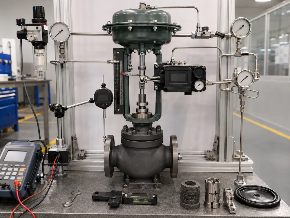
Control valve positioner calibration aligns the input command with actual valve travel, but it should begin only after the valve, actuator, mounting, feedback linkage and instrument-air supply have been checked, and the required fail action has been confirmed. Calibration normally includes confirming direct or reverse action, establishing zero and span or completing the device-specific auto-calibration routine, checking travel at several signal points in both directions, verifying feedback and fail behavior, and recording the final settings. Do not use calibration to hide mechanical stiction, incorrect travel stops, inadequate actuator force, unstable air supply or an oversized valve.
Commissioning Work Pack
Control Valve Positioner Calibration
Objective
Match command to verified valve travel
Applies To
Linear and rotary modulating valves
Primary Evidence
Input, actual travel and feedback record
Package release condition: Positioner calibration confirms the command-to-travel relationship. Final commissioning of the assembled valve–actuator–positioner package is not complete until the valve moves smoothly in both directions, reaches the approved travel limits, reports the correct position and performs the specified failure action.
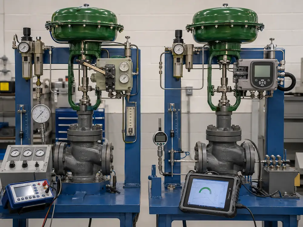
A positioner receives a pneumatic, analog or digital command and regulates actuator pressure or actuator output so that the valve stem or shaft reaches the requested position. Mechanical positioners commonly use zero and span adjustments. Digital valve controllers may use an automated setup routine that identifies travel limits and selects internal tuning parameters.
The exact menu, adjustment sequence and safety procedure depend on the positioner model. The manufacturer’s instruction manual and the project commissioning procedure remain controlling documents. This guide explains the engineering workflow and the evidence that should be collected; it does not replace device-specific instructions.
PHASE 1
Release
Prove the assembly is safe and mechanically ready.
PHASE 2
Configure
Confirm actuator, signal, action and feedback settings.
PHASE 3
Calibrate
Establish zero/span or run the approved setup routine.
PHASE 4
Verify
Test travel, feedback, response and failure behavior.
PHASE 5
Record
Save settings, test results and release status.
PHASE 1 · RELEASE
Do Not Calibrate an Unreleased Valve Assembly
A positioner can only position the mechanism connected to it. If the coupling slips, the actuator is misaligned, the travel stop is wrong or packing friction is excessive, repeated calibration will not create a reliable control valve.
Before applying a calibration signal, confirm the approved work permit, isolation and energy-control requirements. For an installed valve, determine whether moving it can disturb the process, bypass an interlock, interrupt cooling, change vessel pressure or expose personnel to stored pneumatic, hydraulic or electrical energy.
Instrument Air, Signal and Test Equipment Release
Pneumatic Supply
Confirm supply pressure at the positioner while the actuator moves. Inspect filtration, drainage, tubing size, fittings, regulator setting and any solenoid or booster in the air path.
Command Source
Use a suitable calibrated signal source or approved control-system output. Confirm whether the device expects pneumatic input, current input, voltage input or digital communication.
Travel Measurement
Verify the mechanical indicator, position feedback, travel sensor or independent measurement method. Command value alone does not prove actual valve position.
Area Classification
Test instruments, communicators, covers, cable entries and work practices must comply with the applicable hazardous-area and electrical requirements.
PHASE 2 · CONFIGURE
Confirm the Configuration Before Adjusting Zero or Span
Incorrect configuration can make a correctly mounted positioner drive in the wrong direction, stop short of full travel or report a false position. Record the required settings before beginning.
| Configuration Item | What to Confirm | Typical Error if Wrong |
|---|---|---|
| Valve motion | Linear or rotary; actual stroke or angle | Incorrect feedback geometry or travel limit |
| Actuator type | Single-acting, double-acting, spring-return, piston or diaphragm | Wrong pneumatic output or failure response |
| Control action | Increasing input opens or closes the valve | Valve moves opposite to controller command |
| Input range | Project signal and any split-range limits | Full travel occurs over the wrong signal range |
| Feedback source | Internal sensor, linkage, shaft pickup or remote sensor | Positioner controls an incorrect or reversed feedback signal |
| Travel limits | Approved mechanical and software limits | Seat overload, incomplete opening or stop impact |
| Failure behavior | Loss of command, air, power and communication | Unexpected movement during an abnormal condition |
PHASE 3 · CALIBRATE
Choose the Correct Calibration Path
PATH A
Mechanical, Pneumatic or Analog Positioner
- Apply the approved minimum command signal.
- Confirm the valve is at the required minimum-travel position.
- Adjust zero using the device-specific method.
- Apply the approved maximum command signal.
- Confirm maximum travel without forcing the mechanical stop.
- Adjust span using the manufacturer’s procedure.
- Repeat minimum and maximum points because zero and span can interact.
- Check intermediate points in both directions.
Do not assume: the adjustment direction, cam, beam, linkage or range spring is identical across positioner models.
PATH B
Digital Valve Controller or Smart Positioner
- Confirm actuator type, travel direction and feedback arrangement.
- Enter or verify the approved signal, travel and actuator configuration.
- Start the manufacturer’s setup or auto-calibration routine only after the valve is released for movement.
- Stop the routine if the actuator strikes stops violently, moves in the wrong direction or cannot complete travel.
- Review reported travel limits, tuning result, alerts and calibration status.
- Apply independent command points to verify the automated result.
- Save the final configuration and device record.
Do not assume: successful auto-calibration proves correct sizing, healthy packing, adequate actuator force or acceptable loop performance.
PHASE 4 · VERIFY
Verify the Complete Travel, Not Only Two Endpoints
Zero and span establish the calibration range, but intermediate checks reveal nonlinearity, mechanical interference, feedback error, hysteresis and direction-dependent behavior. Apply several increasing and decreasing command points across the approved signal range. The exact points, tolerance and number of cycles must follow the project test procedure or manufacturer specification.
| Command Point | Opening Travel | Closing Travel | Reported Feedback | Observation |
|---|---|---|---|---|
| Minimum | Record | Record | Record | Seat approach, stop contact, stability |
| Low intermediate | Record | Record | Record | Stiction, jump, linkage play |
| Mid-travel | Record | Record | Record | Position stability and response |
| High intermediate | Record | Record | Record | Restriction or actuator limitation |
| Maximum | Record | Record | Record | Full travel without stop overload |
The table is a recording format, not a universal acceptance standard. Allowable deviation, deadband, hysteresis, settling time and response criteria should come from the approved valve datasheet, positioner specification, project procedure or applicable test standard.
Five Acceptance Gates Before Release
GATE 1
Direction
Commands move the valve in the approved direction.
GATE 2
Travel
Stroke or angle matches the approved range without stop impact.
GATE 3
Repeatability
The valve returns consistently from both directions.
GATE 4
Feedback
Local and transmitted position match actual travel.
GATE 5
Failure Response
The package performs the specified failure action.
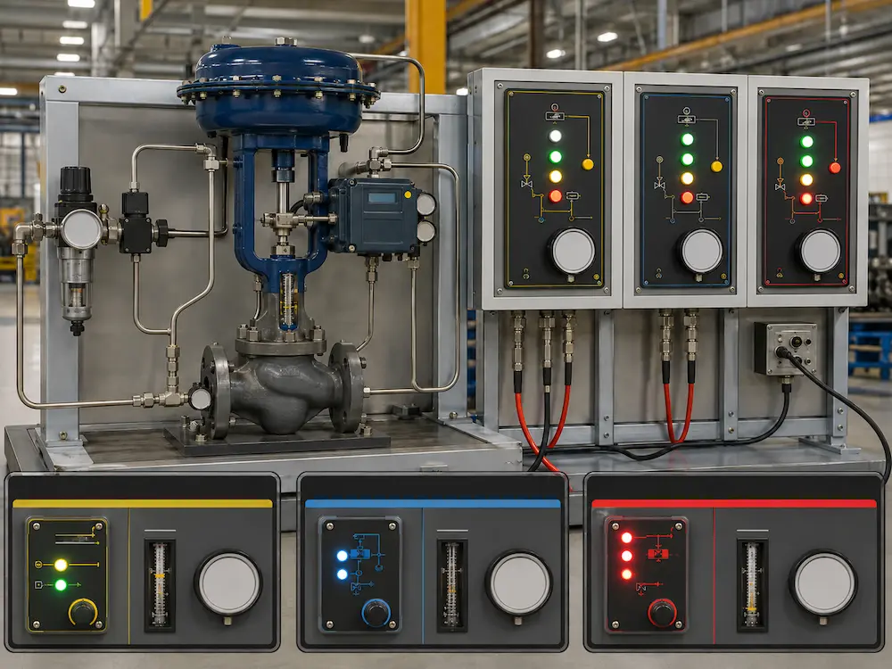
Signal Failure, Air Failure and Power Failure Are Separate Tests
One failure test cannot represent every abnormal condition. The commissioning procedure should state which failures must be simulated and what result is expected.
Loss of Command Signal
Verify configured signal-failure response, alarm and position behavior.
Loss of Instrument Air
Verify actuator spring action, lock-up system or other pneumatic failure design.
Loss of Electrical Power
Verify I/P devices, digital controllers, solenoids and stored-energy systems.
Loss of Communication
Verify fallback behavior, local control state and diagnostic indication.
The required safe position should come from the process safety assessment. For broader actuator-package requirements, use the Valve Actuator Selection Guide.
When Calibration Does Not Hold
| Observed Result | Likely Cause Layer | Required Decision |
|---|---|---|
| Zero shifts after several strokes | Loose linkage, coupling slip, unstable feedback mount or mechanical settling | Correct the assembly and repeat calibration |
| Opening and closing positions differ | Friction, backlash, deadband, packing load or linkage geometry | Investigate mechanical response before retuning |
| Auto-calibration cannot find full travel | Wrong configuration, low supply pressure, stop restriction, feedback error or insufficient force | Stop the routine and verify package configuration |
| Valve oscillates after calibration | Positioner gain, booster bypass, air restriction, stiction, loop tuning or excessive valve gain | Use the Control Valve Hunting Guide |
| Feedback is correct but process control is poor | Valve sizing, installed characteristic, sensor location or controller tuning | Separate valve travel performance from process-loop performance |
| Valve reaches full travel but cannot shut off | Seat damage, incorrect seat load, trim wear, debris or actuator force limitation | Perform leakage and mechanical inspection |
PHASE 5 · RECORD
Positioner Calibration Record
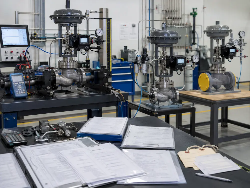
A repeatable calibration process ends with an auditable record. The exact fields depend on the project, but the record should identify the complete valve package and the conditions under which it was tested.
Recommended Supporting Records
- Approved valve and actuator datasheets
- Positioner configuration or parameter report
- Opening and closing travel results
- Signal and position-feedback verification
- Failure-action test result
- Instrument calibration certificates where required
- Air-supply condition and test pressure
- Photos of final mounting, tubing and identification
- Outstanding punch items and corrective actions
Factory Calibration vs Site Loop Verification
Factory Package Test
Confirms the assembled valve, actuator, positioner, tubing and accessories can perform the specified mechanical and control functions before shipment.
- Mounting and travel verification
- Positioner setup and calibration
- Command and feedback check
- Fail-action functional test
- Valve pressure and leakage tests as specified
- Final configuration and documentation
Site Loop Verification
Confirms the installed package communicates correctly with the plant system and still performs after transport, installation and field wiring or tubing.
- DCS or PLC command path
- Actual position-feedback path
- Instrument-air supply under site conditions
- Local/remote mode and interlocks
- Alarm and failure-state behavior
- Final stroke or loop check under approved conditions
A factory calibration certificate does not eliminate the need for site verification. Transport, mounting stress, wiring changes, tubing changes, control-system scaling and final process conditions can affect the installed result.
Specify Calibration as Part of the Complete Control Valve Package
Provide the valve tag, process duty, actuator type, minimum air supply, input signal, travel range, fail action, feedback requirement, hazardous-area classification and required inspection records. Vcore Valve can coordinate valve assembly, positioner configuration, functional stroke testing and project documentation before shipment.
Related Technical Resources
Technical References
ANSI/ISA-75.13.01 provides standardized methods for evaluating the performance of analog-input, pneumatic-output positioners. It is not a universal field-calibration procedure for every positioner model. Device-specific calibration steps and acceptance limits must come from the approved manufacturer manual and project procedure.
Frequently Asked Questions
What is control valve positioner calibration?
Positioner calibration aligns the command signal with actual valve travel. It normally includes confirming action and range, establishing zero and span or running a device-specific automatic setup, and verifying intermediate travel points, feedback and failure behavior.
What is zero and span in a valve positioner?
Zero establishes the valve position corresponding to the minimum approved input, while span establishes the travel range between minimum and maximum input. On mechanical positioners the adjustments may interact, so both endpoints are rechecked. Digital devices may determine them through an automated routine.
Does auto-calibration prove the control valve is healthy?
No. A successful routine does not prove correct valve sizing, acceptable packing friction, sufficient actuator force, healthy trim or good process-loop tuning. Independent travel and functional checks are still required.
Why does positioner calibration keep changing?
Possible causes include loose feedback linkage, coupling slip, unstable air supply, excessive friction, mechanical wear, temperature effects, incorrect mounting geometry or an actuator and valve assembly that does not move repeatably.
Should a positioner be calibrated at the factory or at site?
The assembled package should be calibrated and functionally tested at the factory when supplied as a complete unit. Site verification is still required to confirm final air supply, wiring, control-system scaling, feedback, interlocks and installation condition.
Is direct action the same as fail-open?
No. Direct or reverse action describes how valve travel changes as the command changes. Fail-open, fail-close or fail-in-place describes the package response to a specified loss of air, signal, power or communication.