Vcore Valve · Engineered Product Configuration
Compact Threaded Isolation Valve with a Union Bonnet
For industrial skid builders, piping contractors and valve distributors, a small gate valve must match more than the nominal pipe diameter. The bonnet joint, valve-body material, thread form, packing and end-to-end envelope all affect installation and replacement compatibility.
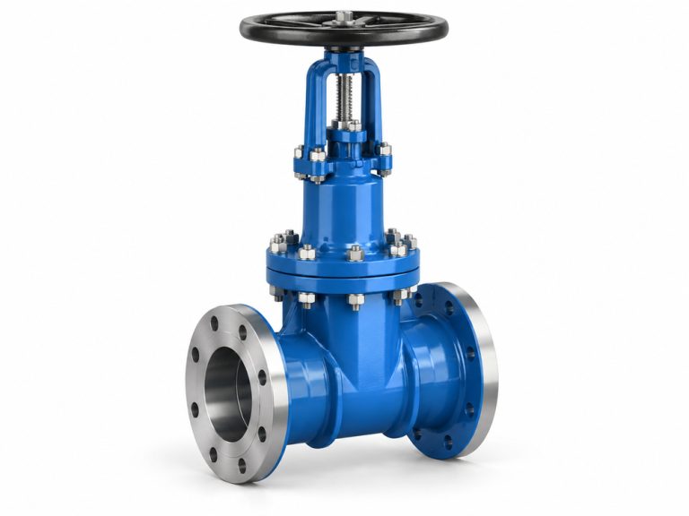
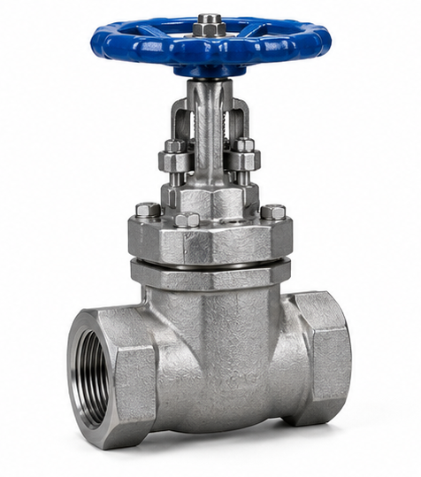
This product page describes a cast steel union bonnet gate valve with female NPT ends. The valve is intended for fully open or fully closed service; it is not intended for routine throttling or precision flow control.
Explore our broader industrial gate valve range for other end connections and bonnet constructions.
Technical Specifications
| Item | Proposed / project-confirmed configuration |
|---|---|
| Product type | Small-bore, manual, metal-seated gate valve |
| Bonnet connection | Union bonnet; union nut and joint detail per approved sectional drawing |
| Body material | ASTM A216 Grade WCB cast carbon steel (not ASTM A105 forged steel) |
| Nominal sizes | 1″, 1¼″, 1½″, 2″ (NPS); other sizes by drawing review |
| End connection | Female NPT threaded ends; thread dimensions and engagement per ASME B1.20.1 when specified |
| Stem and trim | SS420 family / project-designated material grade; exact stem, wedge and seat component materials to be identified on BOM |
| Seating | Metal seat with Stellite hard-facing where specified; deposit location, grade and finished thickness per approved trim drawing |
| Stem configuration | Rising or non-rising arrangement: to be confirmed from the offered model and GA drawing |
| Operator | Manual handwheel |
| Design / rating | Specify the applicable design standard, pressure class and pressure-temperature rating at inquiry; ASME B16.34 requirements only when expressly included in the approved design scope |
| Testing | Shell, seat leakage and functional testing to agreed standard and acceptance criteria (e.g., API 598 if applicable to the approved design) |
| Media / temperature | Project-specific compatible water, oil, gas or utility service; confirm corrosion, fluid hazard and design temperature prior to selection |
| Options | Project-specific F/F, thread specification, trim, packing, marking and inspection documentation, subject to engineering feasibility |
Union Bonnet Construction: What Buyers Should Check
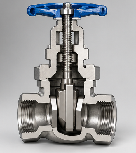
A union bonnet joins the bonnet assembly to the body through a threaded union nut rather than the bolted bonnet arrangement seen on many larger valves. It can support a compact serviceable design, but the joint geometry, gasket or seal, thread engagement and tightening procedure must be engineered for the intended duty.
For replacement projects, request a cross-sectional drawing showing the bonnet nut, body-to-bonnet sealing arrangement, stem packing, backseat if present, wedge travel and seat geometry. A union bonnet does not by itself guarantee lower leakage, higher pressure capability or interchangeability with a bolted-bonnet valve.
WCB Body, SS420 Trim and Stellite Seat: Separate Material Requirements
ASTM A216 WCB refers to a cast carbon steel body material. It is not interchangeable with forged ASTM A105 merely because both are carbon steels. Specify WCB casting requirements and any material-test documentation on the purchase order.
SS420 should be written as an exact material grade/standard on the approved parts list, not treated as a sufficient description for every internal component. Confirm stem, wedge, seat-ring and backseat materials individually.
Stellite hard-facing is applied to designated sealing contact surfaces to improve resistance to wear and galling in a suitable design. Confirm the hard-facing alloy, applied locations, finished layer thickness and inspection criteria. It does not independently establish zero leakage or compatibility with every fluid.
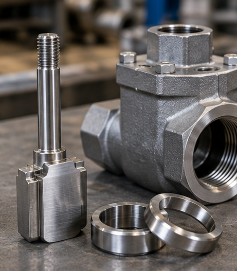
Face-to-Face (F/F) and Threaded End Dimensions
Short-body threaded valves are often purchased for existing skids or tight piping envelopes. The F/F dimension is the axial distance between the two outer end faces of the valve; it is not the threaded engagement length, center-to-handwheel height or installed pipe-to-pipe gap. These dimensions must be identified separately on the general arrangement (GA) drawing.
| Nominal size (NPS) | Nominal DN reference | F/F target from current project | Dimensional approval |
|---|---|---|---|
| 1″ | DN25 | 47 mm | Drawing confirmation required |
| 1¼″ | DN32 | To be confirmed | Do not infer from adjacent sizes |
| 1½″ | DN40 | 64 mm | Drawing confirmation required |
| 2″ | DN50 | 78 mm | Drawing confirmation required |
These are project-specific target dimensions supplied for a particular enquiry, not published ASME B16.10 dimensions or a universal size chart. Actual manufacturability, dimensional tolerance and final F/F are subject to factory-approved drawings.
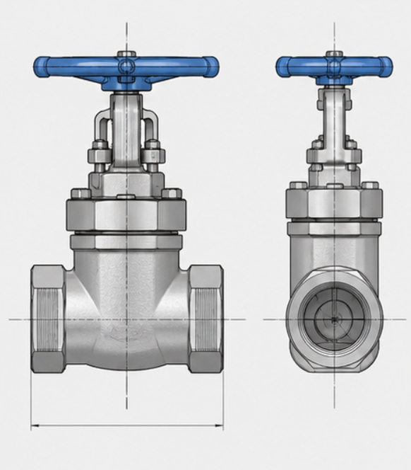
Drawing-Based Customization Checklist
- Submit the existing valve/sample or a dimensioned drawing with F/F, overall height and handwheel diameter.
- Specify female NPT size, thread standard, thread depth and mating pipe/thread compatibility. NPT, BSPT and BSPP are not interchangeable specifications.
- Identify stem type, bonnet-joint details, wedge travel, flow-port requirements and required minimum wall thickness.
- Confirm body/bonnet, wedge, stem, seat and hard-facing material designations separately.
- State design pressure, design temperature, medium, testing criteria, marking, quantity and inspection documents.
Typical Industrial Applications
Equipment and Utility Piping
Manual isolation of compatible industrial utility lines, auxiliary process connections and OEM equipment piping where threaded ends and a compact installation envelope are specified.
Replacement and Maintenance
Drawing-matched replacement on existing skids or piping assemblies where an incorrect F/F dimension or wrong thread form could require field rework.
Distributor and Project Supply
Controlled batch orders using a common approved drawing, trim schedule, material documentation and inspection plan.

Factory Inspection and Supply Documentation
Before shipment, agree an inspection and test plan that covers material identification, dimensional verification, NPT thread gauging, bonnet-joint assembly, valve operation, shell integrity and seat leakage testing. Select test pressures, hold times and acceptance criteria from the actual applicable design/test standard and approved rating, rather than from the nominal size alone.

Available project documentation may include the approved GA and sectional drawing, bill of materials, material certificates, dimensional inspection report, pressure-test records and packing list, as specified in the purchase order.
Related Gate Valve Solutions
For a broader comparison of bonnet styles, stem arrangements and end connections, browse the Vcore Gate Valve product category. For an external rising-stem arrangement, see the Rising Stem Gate Valve for Industrial Pipeline Isolation. For larger piping that requires bolted flanged ends rather than female NPT ends, review the Double Flanged Gate Valve. These are distinct configurations; request a technical comparison before substitution.
Frequently Asked Questions
What is the difference between a union bonnet and a bolted bonnet gate valve?
A union bonnet uses a union-nut connection at the body/bonnet joint, while a bolted bonnet uses bolting to secure the bonnet. The joint design and rating must be verified for the chosen model; neither arrangement alone determines the maximum service pressure.
Is this union bonnet gate valve made from A105 forged steel?
The configuration described here specifies an ASTM A216 WCB cast steel body. ASTM A105 is a separate forged carbon steel material and must not be substituted without a revised design and purchase-order approval.
Can a female NPT gate valve be connected to BSP pipe threads?
No direct interchangeability should be assumed. NPT and BSP thread forms and sealing practices differ. Confirm both mating connections and use the specified compatible threaded-end configuration.
Is 1¼-inch F/F available at a fixed length?
Not from the current project data. Supply the replacement sample or required F/F length, and request a factory-approved dimensioned drawing before placing the order.
Can this gate valve be used to regulate flow?
It is designed primarily for full-open/full-close isolation; prolonged partial opening can damage the wedge and seats. Choose an appropriately engineered globe or control valve for routine throttling.
Request a Drawing-Matched Quotation
Send Vcore Valve your NPS size, required F/F dimension, female NPT thread standard, design pressure and temperature, medium, WCB/SS420/Stellite material schedule, quantity and project drawings. We can review the required configuration and confirm technical and commercial details against the approved factory offer.
Website: www.onoffvalve.com | Explore Gate Valves